Transmission Replacement (L84, L87, 2WD without F47)
Automatic Transmission - 10L80 MHS MQC | Repair Instructions - On Vehicle | Document ID: 5608378 Single Use Fasteners and Components Exhaust System Seal [2x] Transmission Fluid Cooler Seal Special Tools DT-21366 Converter Holding Strap Equivalent regional tools: Special Tools
- Disconnect the battery negative cable. Battery Negative Cable Disconnection and Connection
- Front Wheelhouse Liner - Left Side and Right Side » Remove [2x] — Front Wheelhouse Liner Replacement
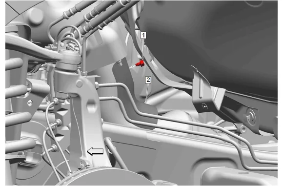
- Exhaust Heat Shield Bolt (1) » Remove
- Exhaust Front Pipe Heat Shield (2) » Remove
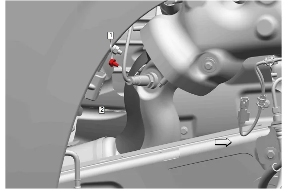
- Exhaust Heat Shield Bolt (1) » Remove
- Exhaust Front Pipe Heat Shield (2) » Remove
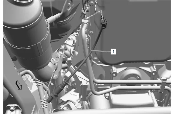
- Disconnect the heated oxygen sensor electrical connector. (1)
- Using a suitable tool, remove the heated oxygen sensor bank 1 sensor 1 (1).
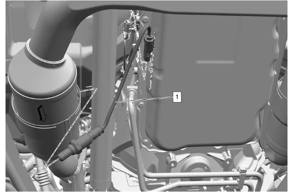
- Disconnect the heated oxygen sensor electrical connector. (1)
- Using a suitable tool, remove the heated oxygen sensor bank 1 sensor 2 (1).
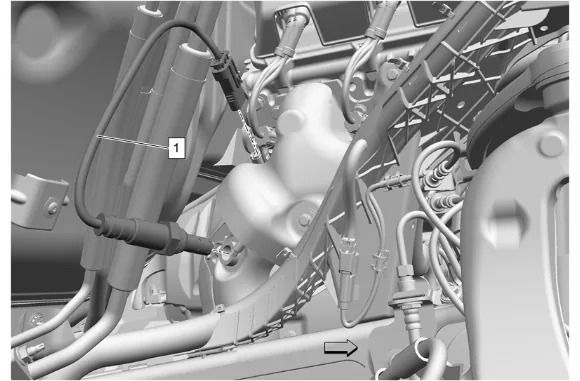
- Disconnect the heated oxygen sensor electrical connector. (1)
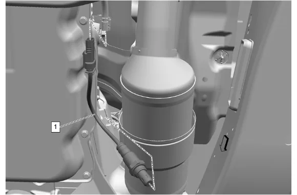
- Disconnect the heated oxygen sensor electrical connector. (1)
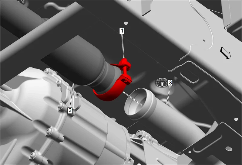
- Exhaust Pipe Clamp (1) » Loosen
- Exhaust Muffler (2) @ Three-Way Catalytic Converter (3) » Separate
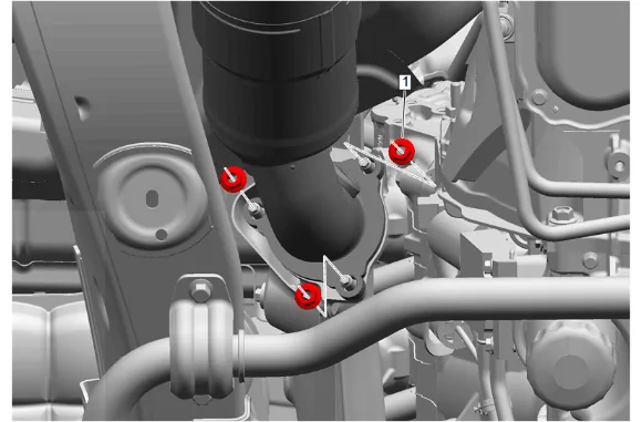
- Exhaust Front Pipe Nut - Left Side (1) » Remove [3x]
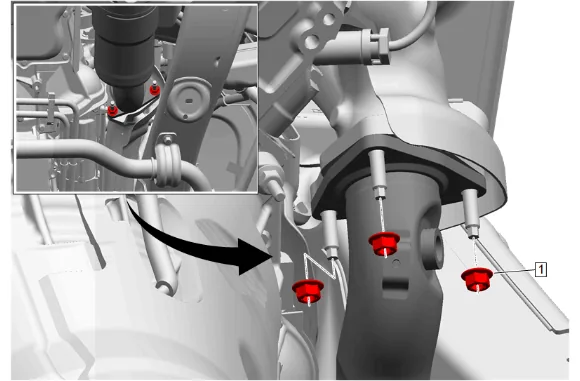
- Exhaust Front Pipe Nut - Right Side (1) » Remove [3x]
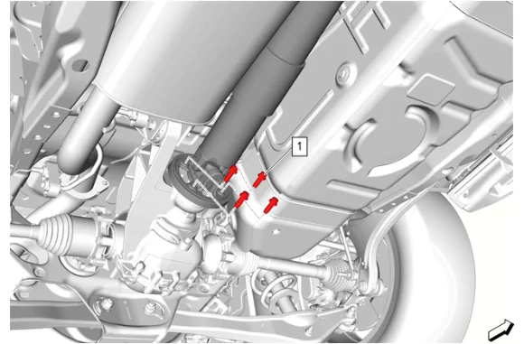
- Mark the relationship of the propeller shaft (2) to the rear wheel drive shaft flange.
- Rear Propeller Shaft Bolt (1) » Remove [4x]
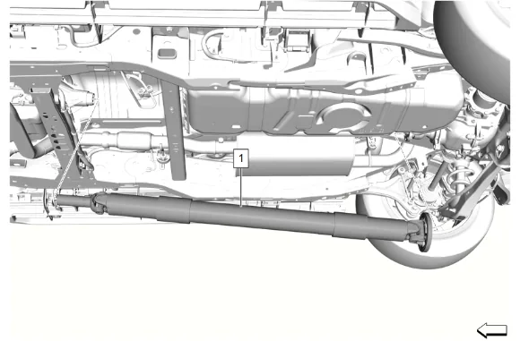
- Propeller Shaft (1) » Remove
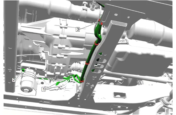
- Remove the 4 wiring harness retainers (3), then reposition the wiring harness as necessary.
- Support the transmission with a suitable jack.
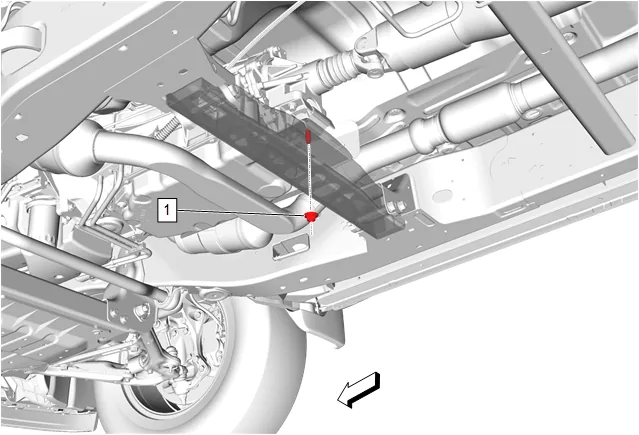
- Transmission Mount Nut (1) » Remove
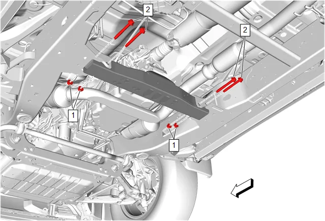
- Transmission Support Crossmember Nut (1) » Remove [4x]
- Transmission Support Crossmember Bolt (2) » Remove [4x]
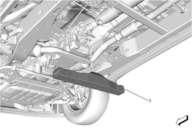
- Transmission Support Crossmember (1) » Remove
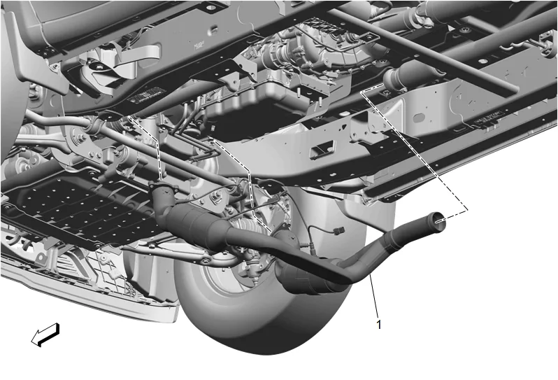
- Three-Way Catalytic Converter (1) » Remove
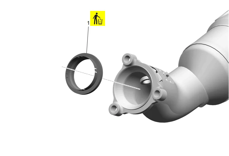
- Exhaust System Seal - Left Side (1) » Remove and DISCARD
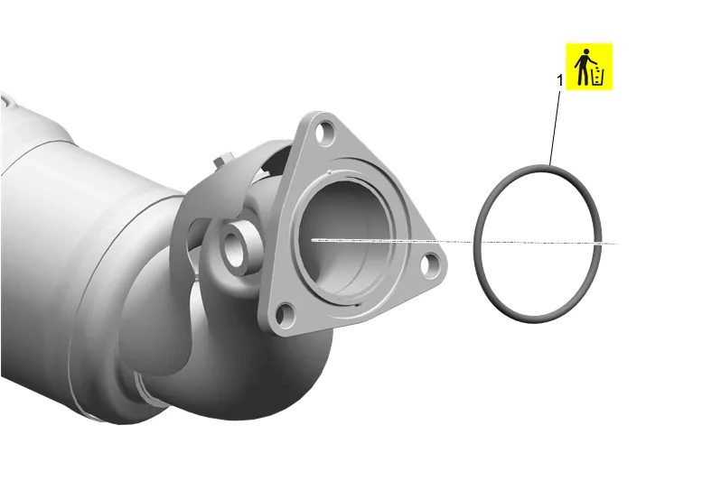
- Exhaust System Seal - Right Side (1) » Remove and DISCARD
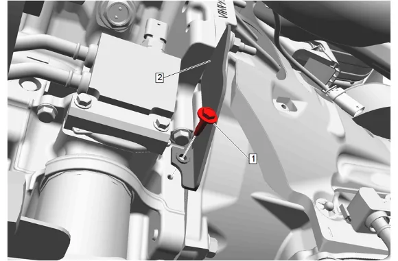
- Transmission Converter Cover Bolt (1) » Remove
- Transmission Converter Cover - Left Side (2) » Remove
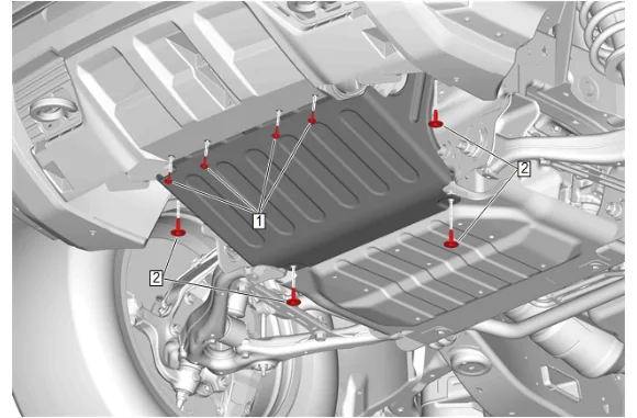
- {with RC1} Front Bumper Fascia Skid Plate Bolt (1) » Remove [4x] 31.1. Underbody Splash Shield Bolt (2) » Remove [4x]
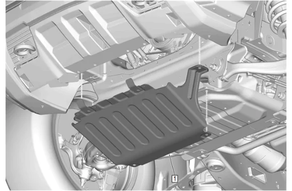
31.2. Underbody Splash Shield (1) » Remove
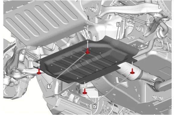
31.3. Underbody Skid Shield Bolt (2) » Remove [2x] 31.4. Underbody Skid Shield (3) » Remove
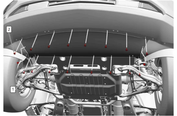
- {with WTX} Front Bumper Fascia Air Deflector Bolt (1) » Remove [10x] 32.1. Front Bumper Fascia Extension Bolt (2) » Remove [8x]
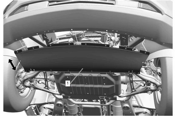
32.2. Pull the front bumper fascia extension (1) rearward and down from the front bumper fascia.
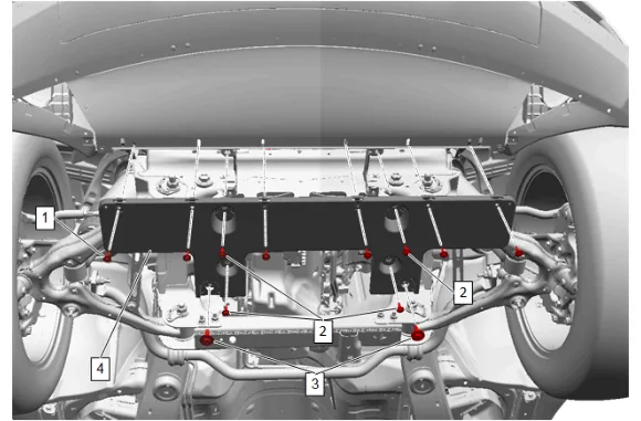
32.3. Front Bumper Fascia Extension Bolt (2) » Remove [4x] 32.4. Front Bumper Fascia Extension Bolt (3) @ Underbody Skid Shield » Remove [2x] 32.5. Front Bumper Fascia Extension (4) » Remove
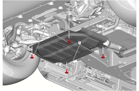
32.6. Underbody Skid Shield Bolt (1) » Remove [2x] 32.7. Underbody Skid Shield (2) » Remove
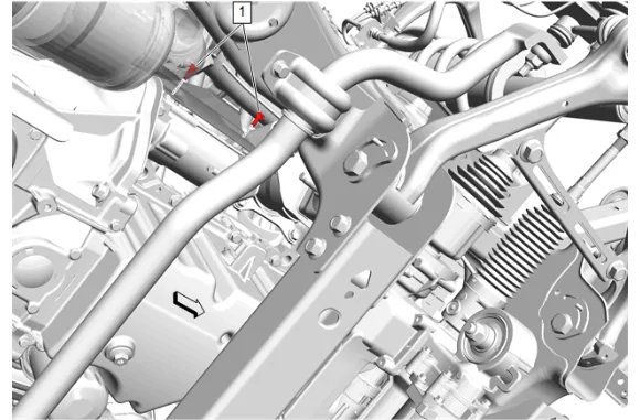
- Starter Heat Shield Bolt (1) » Remove [2x]
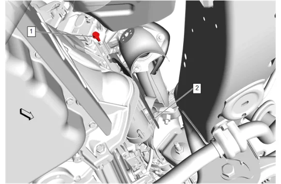
- Starter Heat Shield Bolt (1) » Remove
- Starter Heat Shield (2) » Remove
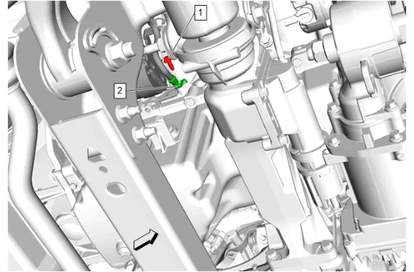
- Battery Negative Cable Ground Bolt (1) » Remove
- Starter Solenoid Cable (2) » Reposition away
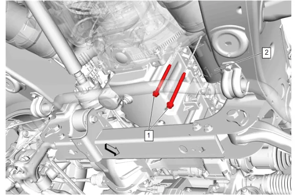
- Starter Bolt (1) » Remove [2x]
- Reposition the starter (2) to access the electrical connections.
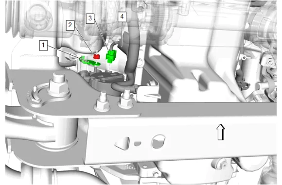
- Protective Sleeve (4) » Reposition
- Starter Solenoid Cable Nut (2) » Remove
- Starter Solenoid Cable (1) » Remove
- Electrical Connector (3) » Disconnect
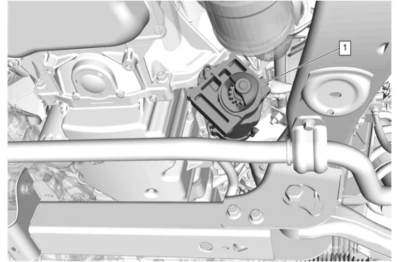
- Starter (1) » Remove
- Place a drain pan under the vehicle.
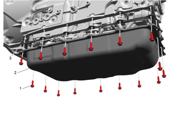
-
Automatic Transmission Fluid Pan Bolt (1) » Remove [16x]
-
Automatic Transmission Fluid Pan (2) » Remove
-
Automatic Transmission Fluid Pan Gasket (3) » Remove
-
Allow the transmission to drain.
-
Automatic Transmission Fluid Pan Gasket (3) » Install
-
Automatic Transmission Fluid Pan (2) » Install
-
Automatic Transmission Fluid Pan Bolt (1) » Install and hand tighten [16x]
-
Remove the drain pan.
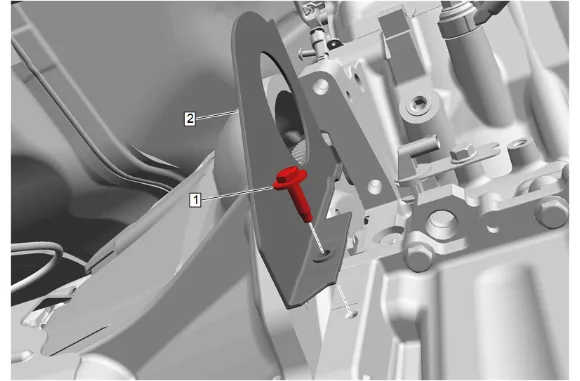
- Transmission Converter Cover Bolt (1) » Remove
- Transmission Converter Cover - Right Side (2) » Remove
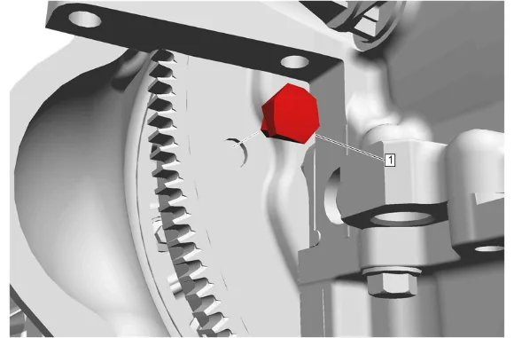
- Repeat the following steps for all transmission torque converter bolts (1): 56.1. Rotate the crankshaft balancer center bolt clockwise ONLY, to align the transmission torque converter bolt with the starter opening. 56.2. Transmission Torque Converter Bolt (1) » Remove [6x]
- Lower the transmission enough to gain access to the transmission vent hose clip bracket.
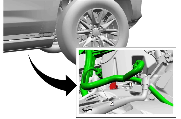
- Remove the engine wiring harness retainer (1) and reposition the engine wiring harness (2) as necessary.
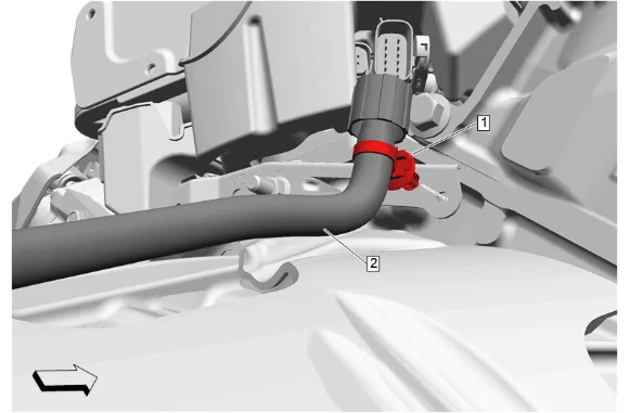
- Remove the transmission vent hose retainer (1) then reposition the transmission vent hose (2) as necessary.
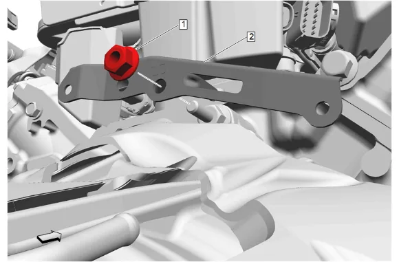
- Remove the transmission vent hose clip bracket nut (1).
- Remove the transmission vent hose clip bracket (2).
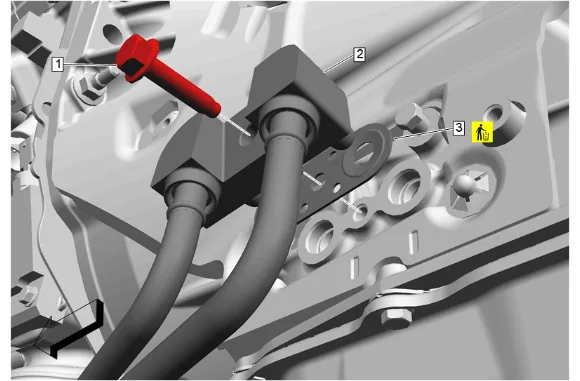
- Transmission Fluid Cooler Pipe Connector Bolt (1) » Remove
- Transmission Fluid Cooler Inlet and Outlet Pipe (2) @ Transmission » Remove
- Transmission Fluid Cooler Seal (3) » Remove and DISCARD
- Cap the fittings and plug the holes when removing the transmission fluid cooler pipes.
- Disconnect the wiring harness retainers.
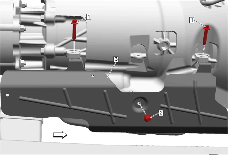
- Transmission Heat Shield Bolt (2) » Remove
- Transmission Heat Shield Bolt (1) » Remove [2x]
- Transmission Heat Shield (3) » Remove
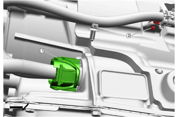
- Disconnect all wiring harness retainers (2) and electrical connectors (1) from the transmission, then position the wiring harness out of the way.
- Cap the opening to prevent contamination.
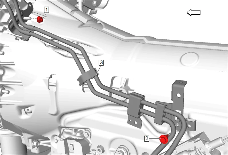
- Fuel Feed and Return Front Hose Bracket Nut (1) » Remove
- Fuel Feed and Return Front Hose Bracket Bolt (2) » Remove
- Reposition the fuel feed and evaporative emission and return hose (3) as necessary.
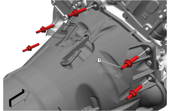
- Transmission Stud (1) Remove [5x]
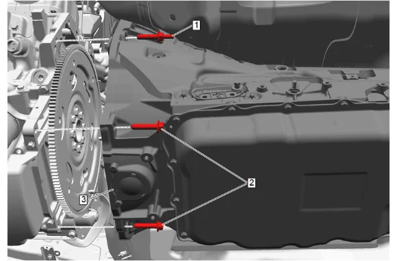
- Transmission Stud (1) Remove
- Transmission Bolt (2) Remove [2x]
- Pull the transmission (3) straight back.
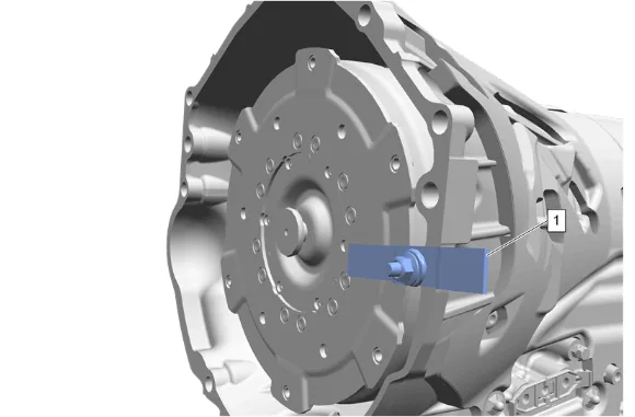
- Install the DT-21366 Converter Holding Strap (1) onto the transmission bell housing to retain the torque converter.
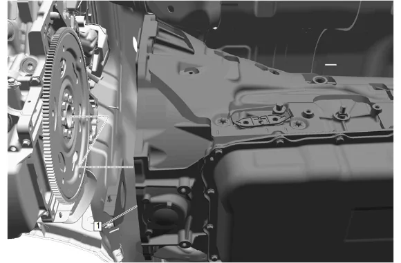
- Automatic Transmission (1) » Remove
-
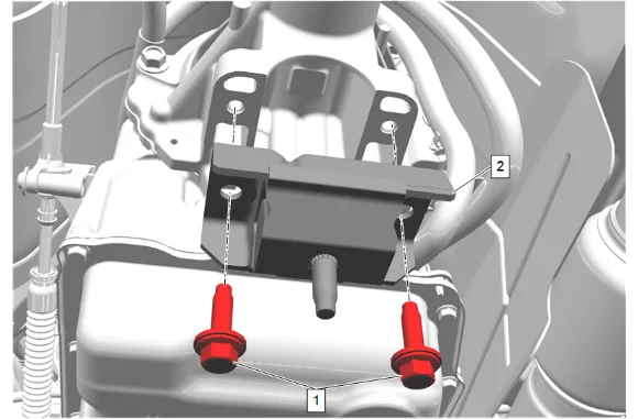
Transmission Mount Bolt (1) » Remove [2x]
-
Transmission Mount (2) » Remove Installation Procedure
-
Note the new transmission unique number (TUN).
-
Support the transmission with a suitable transmission jack.
-
Transmission Mount (2) » Install
-
If NEW threaded components are being installed, loosen the adhesive using a metal pick or similar tool before proceeding. If threaded components are reused, prepare the threaded components using the following steps: 4.1. Remove any loose cured adhesive from the external threads of the components using a lint free cloth. 4.2. Thread the cleaned components into the internal mating threads and remove to loosen trapped cured adhesive. 4.3. Apply thread locking adhesive to the external threads of the components. Adhesives, Fluids, Lubricants, and Sealers 4.4. Ensure there are no gaps in the thread locking adhesive once applied to the component.
-
Transmission Mount Bolt (1) » Install and tighten [2x] — Fastener Specifications
-
Install the DT-21366 Converter Holding Strap (1) onto the transmission bell housing to retain the torque converter.
-
Raise the transmission (1) into place.
-
Remove the DT-21366 Converter Holding Strap (1).
- Slide the transmission (3) straight onto the locating pins.
-
Transmission Stud (1) Install and tighten — Fastener Specifications
-
Transmission Bolt (2) Install and tighten [2x] — Fastener Specifications
-
Transmission Stud (1) Install and tighten [5x] — Fastener Specifications
-
Install the fuel feed and evaporative emission and return hose (3).
-
Fuel Feed and Return Front Hose Bracket Nut (1) » Install and tighten — Fastener Specifications
-
Fuel Feed and Return Front Hose Bracket Bolt (2) » Install and tighten — Fastener Specifications
-
Install the transmission vent hose clip bracket (2).
-
Install and tighten the transmission vent hose clip bracket nut (1). Fastener Specifications
-
Reposition the transmission vent hose (2) then install transmission vent hose retainer (1).
-
Reposition the engine wiring harness (2) then install the engine wiring harness retainer (1).
-
Transmission Heat Shield (3) » Install
-
If NEW threaded components are being installed, loosen the adhesive using a metal pick or similar tool before proceeding. If threaded components are reused, prepare the threaded components using the following steps: 21.1. Remove any loose cured adhesive from the external threads of the components using a lint free cloth. 21.2. Thread the cleaned components into the internal mating threads and remove to loosen trapped cured adhesive. 21.3. Apply thread locking adhesive to the external threads of the components. Adhesives, Fluids, Lubricants, and Sealers 21.4. Ensure there are no gaps in the thread locking adhesive once applied to the component.
-
Transmission Heat Shield Bolt (2) » Install and tighten — Fastener Specifications
-
Transmission Heat Shield Bolt (1) » Install and tighten [2x] — Fastener Specifications
-
Install the wiring harness.
-
Uncap the fittings and unplug the holes of the transmission.
-
Connect the wiring harness retainers. (2)
-
Connect the electrical connector. (1)
-
If NEW threaded components are being installed, loosen the adhesive using a metal pick or similar tool before proceeding. If threaded components are reused, prepare the threaded components using the following steps: 28.1. Remove any loose cured adhesive from the external threads of the components using a lint free cloth. 28.2. Thread the cleaned components into the internal mating threads and remove to loosen trapped cured adhesive. 28.3. Apply thread locking adhesive to the external threads of the components. Adhesives, Fluids, Lubricants, and Sealers 28.4. Ensure there are no gaps in the thread locking adhesive once applied to the component.
-
Transmission Torque Converter Bolt (1) » Install and tighten [6x] — Fastener Specifications
-
Transmission Converter Cover - Right Side (2) » Install
-
Transmission Converter Cover Bolt (1) » Install and tighten — Fastener Specifications
-
Starter (1) » Install
-
Electrical Connector (3) » Connect
-
Protective Sleeve (4) » Install
-
Starter Solenoid Cable (1) » Install
-
Starter Solenoid Cable Nut (2) » Install and tighten — Fastener Specifications
-
Starter Bolt (1) » Install and tighten [2x] — Fastener Specifications
-
Starter Solenoid Cable (2) » Install
-
Battery Negative Cable Ground Bolt (1) » Install and tighten — Fastener Specifications
-
Starter Heat Shield (2) » Install
-
Starter Heat Shield Bolt (1) » Install and tighten — Fastener Specifications
-
Starter Heat Shield Bolt (1) » Install and tighten [2x] — Fastener Specifications
-
{with RC1} Underbody Skid Shield (3) » Install 43.1. Underbody Skid Shield Bolt (2) » Install and tighten [2x] — Fastener Specifications
43.2. Underbody Splash Shield (1) » Install
43.3. Underbody Splash Shield Bolt (1) » Install and tighten [4x] — Fastener Specifications 43.4. Underbody Splash Shield Bolt (2) » Install and tighten [4x] — Fastener Specifications
- {with WTX} Underbody Skid Shield (2) » Install 44.1. Underbody Skid Shield Bolt (1) » Install and tighten [2x] — Fastener Specifications
44.2. Front Bumper Fascia Extension (4) » Install 44.3. Front Bumper Fascia Extension Bolt (3) @ Underbody Skid Shield » Install and tighten [2x] — Fastener Specifications 44.4. Front Bumper Fascia Extension Bolt (2) » Install and tighten [4x] — Fastener Specifications
44.5. Front Bumper Fascia Extension (1) » Install
44.6. Front Bumper Fascia Extension Bolt (2) » Install and tighten [8x] — Fastener Specifications 44.7. Front Bumper Fascia Air Deflector Bolt (1) » Install and tighten [10x] — Fastener Specifications
-
Transmission Converter Cover - Left Side (2) » Install
-
Transmission Converter Cover Bolt (1) » Install and tighten — Fastener Specifications
-
Propeller Shaft (1) » Install
-
Align the reference marks made between the rear wheel drive shaft flange and the front and rear propeller shaft (2).
-
If NEW threaded components are being installed, loosen the adhesive using a metal pick or similar tool before proceeding. If threaded components are reused, prepare the threaded components using the following steps: 49.1. Remove any loose cured adhesive from the external threads of the components using a lint free cloth. 49.2. Thread the cleaned components into the internal mating threads and remove to loosen trapped cured adhesive. 49.3. Apply thread locking adhesive to the external threads of the components. Adhesives, Fluids, Lubricants, and Sealers 49.4. Ensure there are no gaps in the thread locking adhesive once applied to the component.
-
Install the 4 rear propeller shaft bolts (1) and tighten in a crisscross pattern. Fastener Specifications.
-
Exhaust System Seal - Right Side (1) » Install NEW
-
Exhaust System Seal - Left Side (1) » Install NEW
-
Three-Way Catalytic Converter (1) » Install
-
Transmission Support Crossmember (1) » Install
-
Transmission Support Crossmember Bolt (2) » Install [4x]
-
Transmission Support Crossmember Nut (1) » Install and tighten [4x] — Fastener Specifications
-
Transmission Mount Nut (1) » Install and tighten — Fastener Specifications
-
Remove the support from the transmission.
-
Install the wiring harness as necessary and connect the 4 wiring harness retainers (3).
-
Exhaust Front Pipe Nut - Right Side (1) » Install and tighten [3x] — Fastener Specifications
-
Exhaust Front Pipe Nut - Left Side (1) » Install and tighten [3x] — Fastener Specifications
-
Exhaust Muffler (2) @ Three-Way Catalytic Converter (3) » Connect
-
Exhaust Pipe Clamp (1) » Tighten — Fastener Specifications
-
Connect the heated oxygen sensor electrical connector. (1)
-
Connect the heated oxygen sensor electrical connector. (1)
-
Using a suitable tool, install and tighten the heated oxygen sensor bank 1 sensor 2 (1). Fastener Specifications
-
Connect the heated oxygen sensor electrical connector. (1)
-
Using a suitable tool, install and tighten the heated oxygen sensor bank 1 sensor 1 (1). Fastener Specifications
-
Connect the heated oxygen sensor electrical connector. (1)
-
Exhaust Front Pipe Heat Shield (2) » Install
-
Exhaust Heat Shield Bolt (1) » Install and tighten — Fastener Specifications
-
Exhaust Front Pipe Heat Shield (2) » Install
-
Exhaust Heat Shield Bolt (1) » Install and tighten — Fastener Specifications
-
Front Wheelhouse Liner - Left Side and Right Side » Install [2x] — Front Wheelhouse Liner Replacement
-
Uncap the fittings and unplug the holes of the transmission.
-
Transmission Fluid Cooler Seal (3) » Install NEW
-
Transmission Fluid Cooler Inlet and Outlet Pipe (2) @ Automatic Transmission » Install
-
Transmission Fluid Cooler Pipe Connector Bolt (1) » Install and tighten — Fastener Specifications
-
Connect the battery negative cable. Battery Negative Cable Disconnection and Connection
-
Fill the transmission to the proper level with NEW transmission fluid. Transmission Fluid Fill Procedure
-
Perform the solenoid valve characterization. Q77 Transmission Control Solenoid Valve Characterization Programming
- Perform the service fast learn procedure. Transmission Service Fast Learn Procedure
- Inspect for Leaks