Transmission Fluid Cooler Inlet and Outlet Pipe Replacement (L84, L87,
Transmission Fluid Cooler Inlet and Outlet Pipe Replacement (L84, L87, 4WD with RC1, with F47) Single Use Fasteners and Components Air Conditioning Compressor and Condenser Hose Seal [2x] Front Differential Carrier Bolt Front Wheel Drive Shaft Nut [2x] Front Wheel Drive Shaft Retaining Ring [2x] Front Wheel Drive Shaft Seal [2x] Transmission Fluid Cooler Pipe Fitting Seal [2x] Transmission Fluid Cooler Seal Special Tools Front Drive Axle EN-45059-A Angle Meter Equivalent regional tools: Special Tools Front Suspension CH-42188-B Ball Joint Separator CH-43631 Ball Joint Separator Equivalent regional tools: Special Tools Wheel Drive Shafts DT-45859 Axle Remover Equivalent regional tools: Special Tools
- Place the air system in service mode.
- Raise the vehicle until the tires are off the ground. Lifting and Jacking the Vehicle
- Using the scan tool, deflate the air spring that will be serviced.
- Disconnect the battery negative cable. Battery Negative Cable Disconnection and Connection
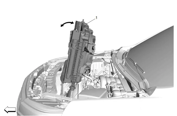
- Remove the condenser, fan, and radiator assembly (1). Condenser, Fan, and Radiator Assembly Removal and Installation
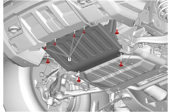
- Front Bumper Fascia Skid Plate Bolt (1) » Remove [4x]
- Underbody Splash Shield Bolt (2) » Remove [4x]
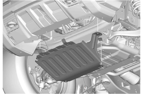
- Underbody Splash Shield (1) » Remove
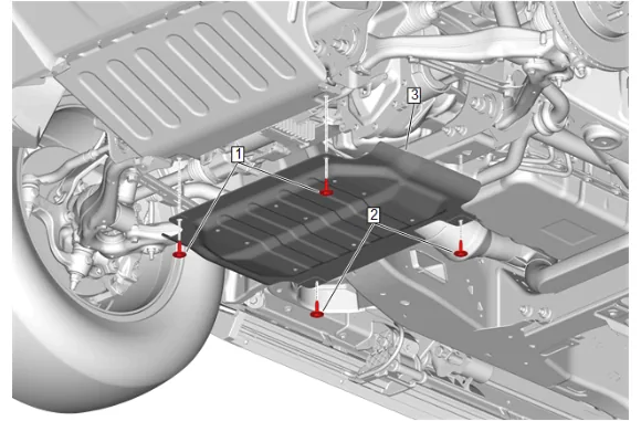
- Underbody Splash Shield Bolt (2) » Remove [2x]
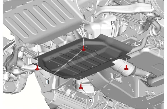
- Underbody Skid Shield (3) » Remove
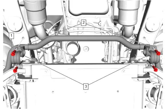
- Front Stabilizer Shaft Bolt (1) » Remove [4x]
- Front Stabilizer Shaft Clamp (2) » Remove [2x]
- Front Stabilizer Shaft Insulator (3) » Remove [2x]
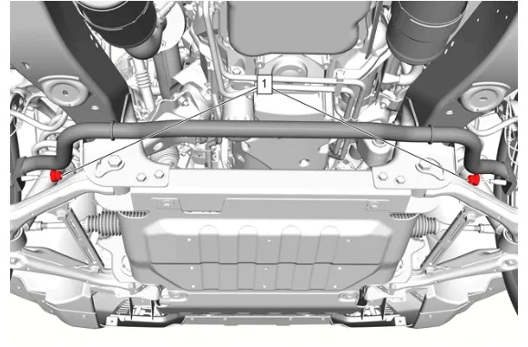
- Front Stabilizer Shaft Link Nut - Upper (1) @ Front Stabilizer Shaft » Remove [2x]
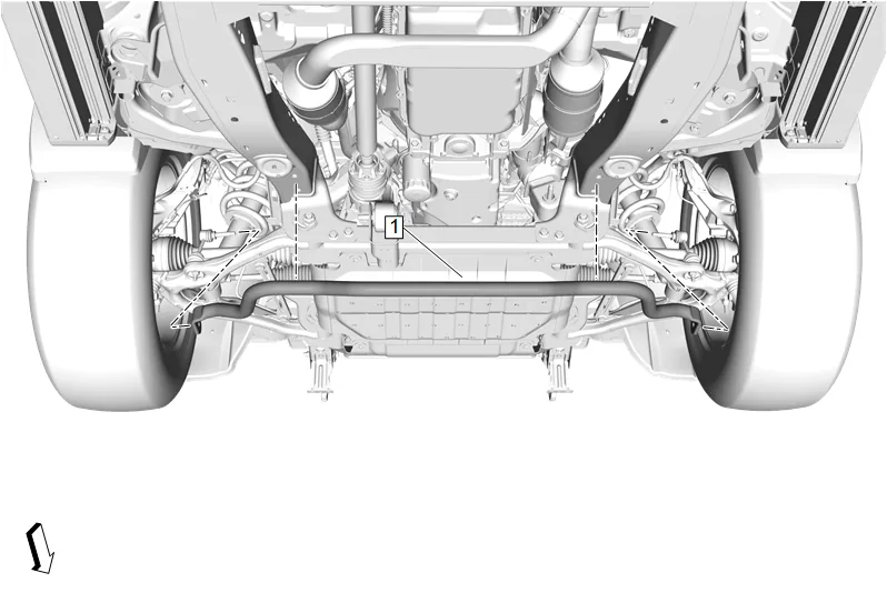
- Front Stabilizer Shaft (1) » Remove
- Remove the front tire and wheel assemblies. Tire and Wheel Removal and Installation
- Have an assistant apply the brakes.
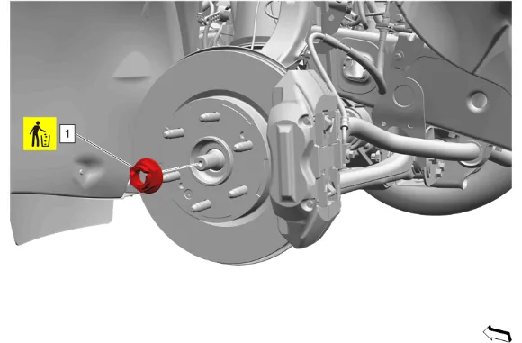
- Front Wheel Drive Shaft Nut (1) » Remove and DISCARD
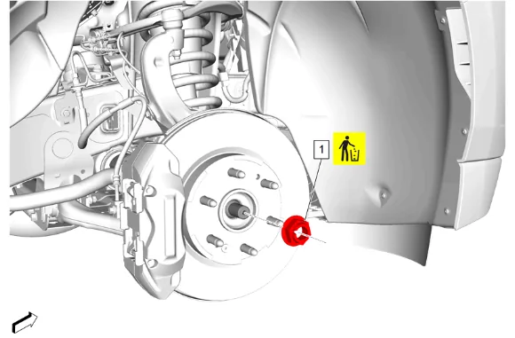
- Front Wheel Drive Shaft Nut (1) » Remove and DISCARD
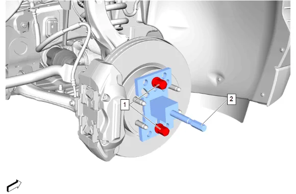
- Install the DT-45859 Axle Remover (2) to the front wheel hub and secure with 2 wheel nuts (1) hand tightened.
- Using the DT-45859 Axle Remover (2), release the front wheel drive half shaft from the front wheel hub.
- Remove the 2 wheel nuts (1) and the DT-45859 Axle Remover (2) from the front wheel hub.
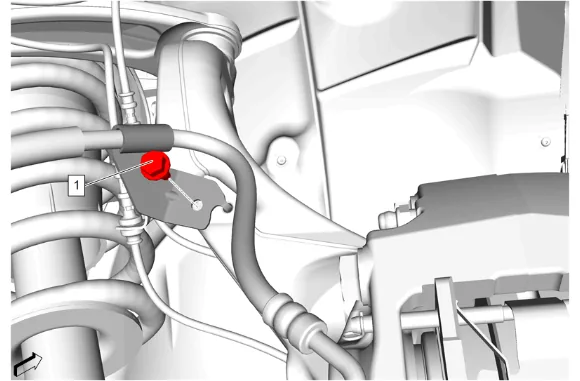
- Front Brake Hose Bracket Bolt (1) » Remove
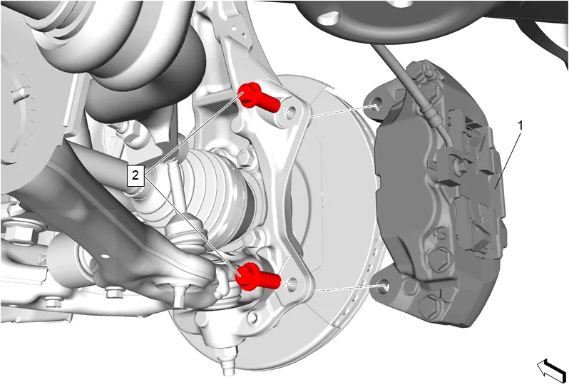
- Front Brake Caliper Bolt (2) » Remove [2x]
- Remove the brake caliper and support with heavy mechanics wire. (1)
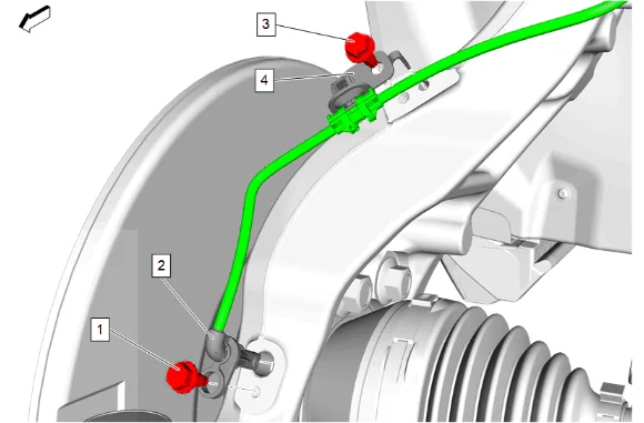
- Front Wheel Speed Sensor Bolt (1) » Remove
- Front Wheel Speed Sensor (2) » Remove
- Front Wheel Speed Sensor Bracket Bolt (3) » Remove
- Front Wheel Speed Sensor Bracket (4) » Remove
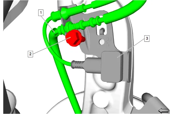
- Electronic Suspension Rear Vertical Accelerometer Bolt (2) » Remove
- Remove the harness (1) and the electronic suspension wheel front vertical accelerometer (3).
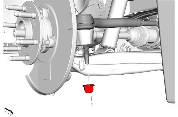
- Steering Linkage Outer Tie Rod Nut (1) » Remove
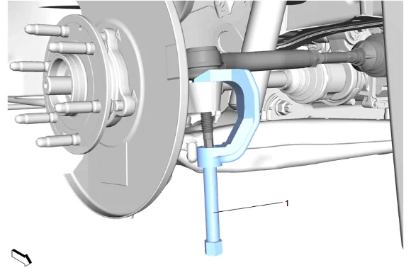
- Using the CH-43631 Ball Joint Separator (1), remove the steering linkage outer tie rod from the steering knuckle.
- Support the lower control arm with a suitable jack stand.
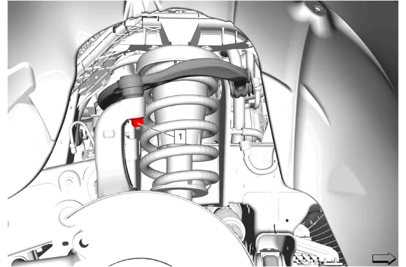
- Front Upper Control Arm Ball Stud Nut (1) » Loosen
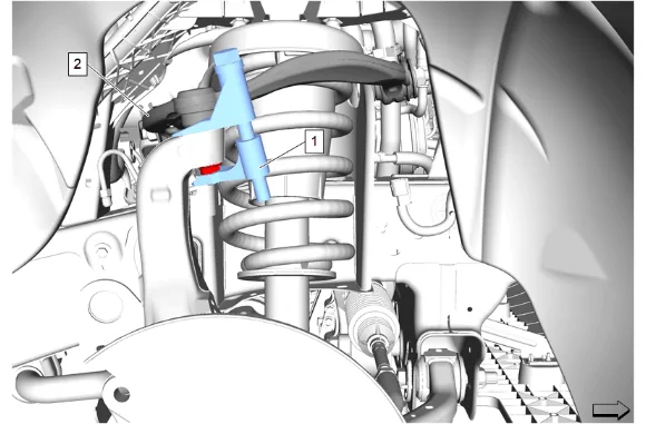
- Using the CH-42188-B Ball Joint Separator (1), separate the right front upper control arm (2) from the steering knuckle.
- Remove the CH-42188-B Ball Joint Separator (1) from the right front upper control arm (2) and the steering knuckle.
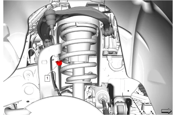
- Front Upper Control Arm Ball Stud Nut (1) » Remove
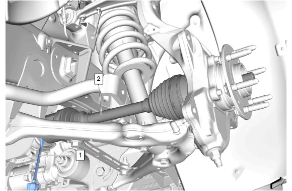
- Using a suitable flat bladed tool (1), release the front wheel drive half shaft (2) from the front differential carrier.
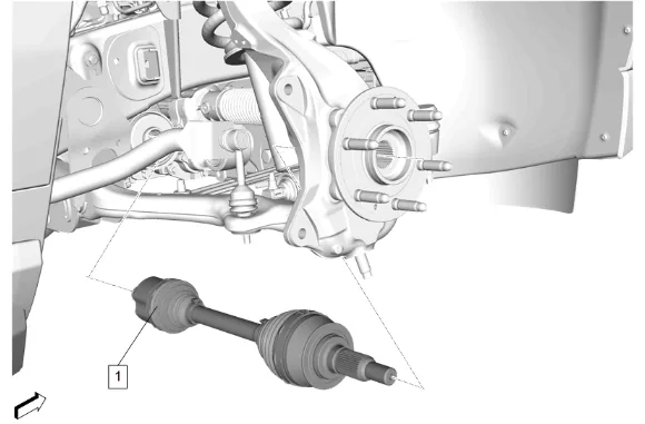
- Remove the front wheel drive half shaft (1) from the front axle.
- Remove the front wheel drive half shaft (1) from the wheel hub.
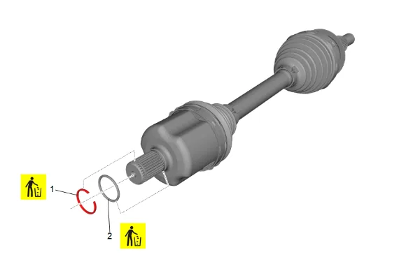
- Front Wheel Drive Shaft Retaining Ring (1) » Remove and DISCARD
- Front Wheel Drive Shaft Seal (2) » Remove and DISCARD
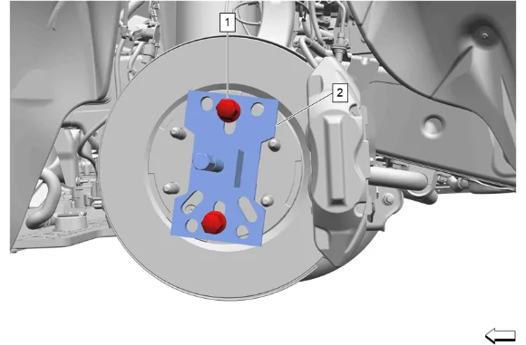
- Install the DT-45859 Axle Remover (2) to the front wheel hub and secure with 2 wheel nuts (1) hand tightened.
- Using the DT-45859 Axle Remover (2), release the front wheel drive half shaft from the front wheel hub.
- Remove the 2 wheel nuts (1) and the DT-45859 Axle Remover (2) from the front wheel hub.
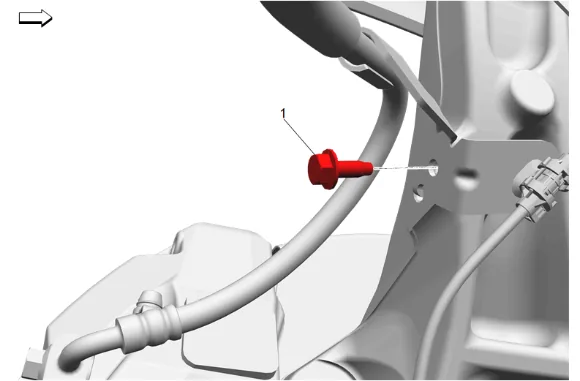
- Front Brake Hose Bracket Bolt (1) » Remove
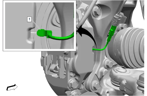
- Front Disc Brake Pad Wear Sensor (1) @ Front Brake Caliper » Remove
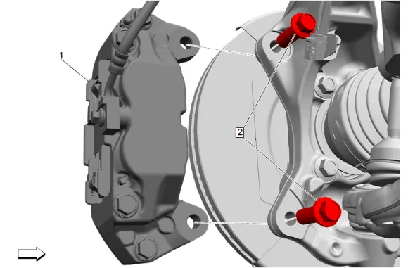
- Front Brake Caliper Bolt (2) » Remove [2x]
- Remove the brake caliper and support with heavy mechanics wire. (1)
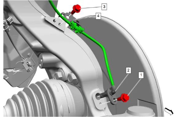
- Front Wheel Speed Sensor Bolt (1) » Remove
- Front Wheel Speed Sensor (2) » Remove
- Front Wheel Speed Sensor Bracket Bolt (3) » Remove
- Front Wheel Speed Sensor Bracket (4) » Remove
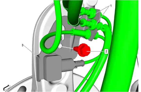
- Electronic Suspension Rear Vertical Accelerometer Bolt (2) » Remove
- Reposition the electronic suspension wheel front vertical accelerometer (3) with the harnesses (1).
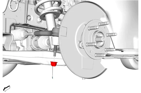
- Steering Linkage Outer Tie Rod Nut (1) » Remove
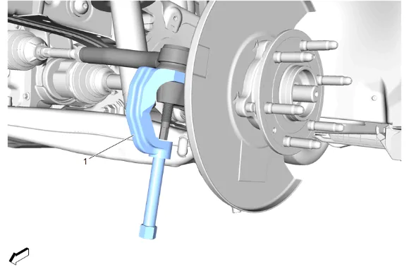
- Using the CH-43631 Ball Joint Separator (1), remove the steering linkage outer tie rod from the steering knuckle.
- Support the lower control arm with a suitable jack stand.
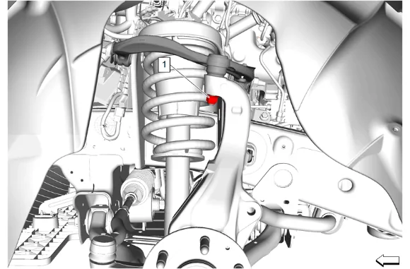
- Front Upper Control Arm Ball Stud Nut (1) » Loosen
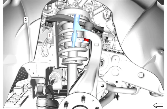
- Using the CH-42188-B Ball Joint Separator (1), separate the left front upper control arm (2) from the steering knuckle.
- Remove the CH-42188-B Ball Joint Separator (1) from the left front upper control arm (2) and the steering knuckle.
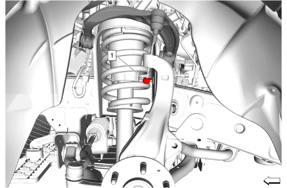
- Front Upper Control Arm Ball Stud Nut (1) » Remove
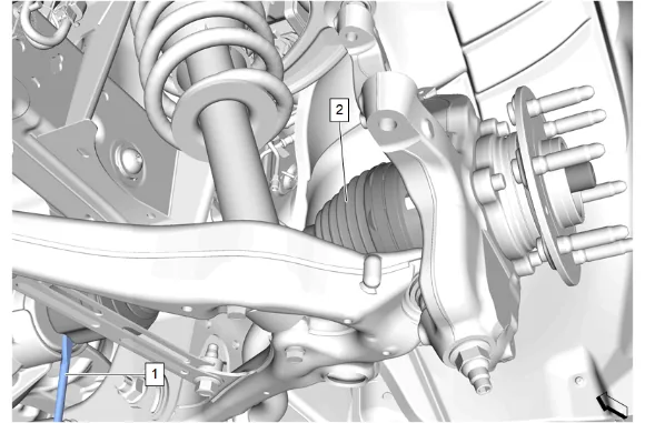
- Using a suitable flat bladed tool (1), release the front wheel drive half shaft (2) from the front differential carrier.
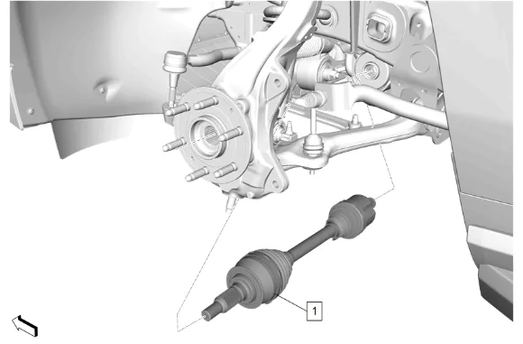
-
Remove the front wheel drive half shaft (1) from the front axle.
-
Remove the front wheel drive half shaft (1) from the wheel hub.
-
Front Wheel Drive Shaft Retaining Ring (1) » Remove and DISCARD
-
Front Wheel Drive Shaft Seal (2) » Remove and DISCARD
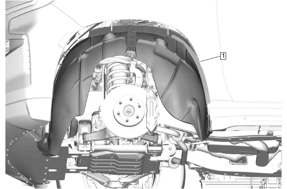
- Front Wheelhouse Liner (1) » Remove — Front Wheelhouse Liner Replacement
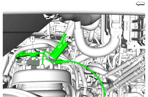
- Disconnect the electrical connector for the electronic suspension wheel front vertical accelerometer (1) and the front air shock harness electrical connector (2).
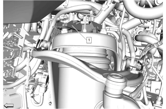
- Unclip and reposition the chassis wiring harness bracket (1) away from the frame shock tower.
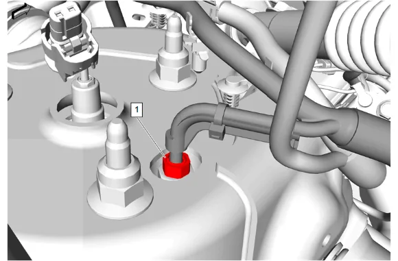
- Disconnect the air line nut (1) and position the air line aside.
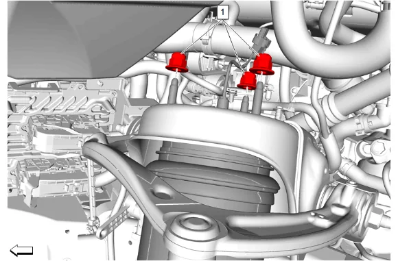
- Front Shock Absorber Nut (1) » Remove [3x]
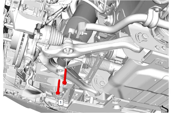
- Front Shock Absorber Bolt (1) » Remove [2x]
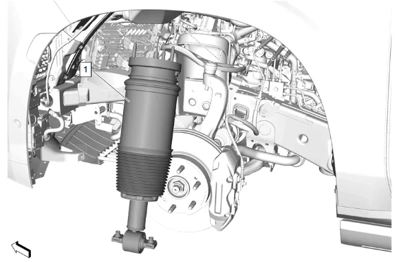
- Front Shock Absorber (1) » Remove
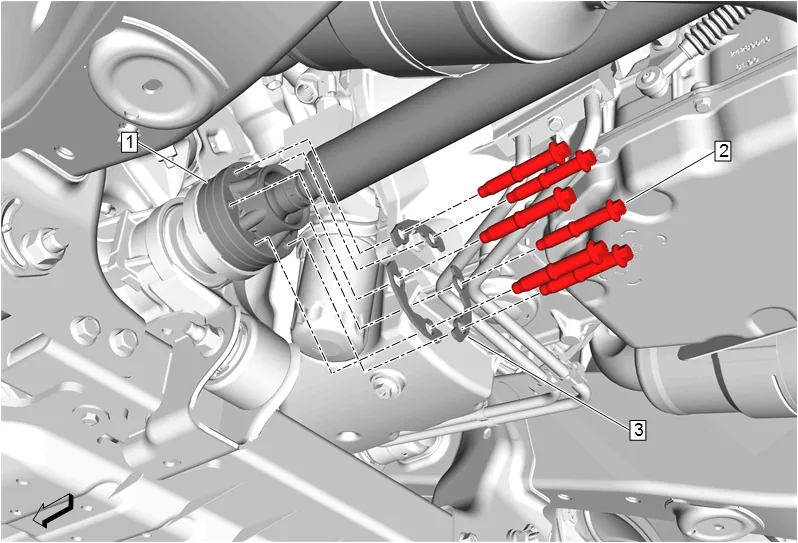
- Mark a reference point between the front axle propeller shaft (1) and the front differential drive pinion gear yoke.
- Front Axle Propeller Shaft Bolt (2) » Remove [6x]
- Front Axle Propeller Shaft Washer (3) » Remove [3x]
- Front Axle Propeller Shaft (1) » Reposition away
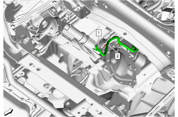
- Disconnect the front drive axle actuator electrical connector (1).
- Release the 2 harness retainers (2) and reposition harness.
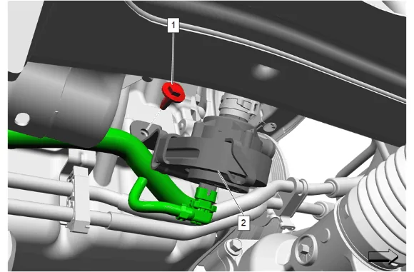
- Electrical Connector @ Heater Coolant Pump (2) » Disconnect
- Heater Water Auxiliary Pump Bolt (1) » Remove
- Remove the heater coolant pump and heater water auxiliary pump bracket (2) as assembly and position aside.
- Support the front axle with a hydraulic jack.
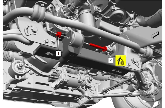
- Front Differential Carrier Nut (1) » Remove
- Front Differential Carrier Bolt (2) » Remove and DISCARD
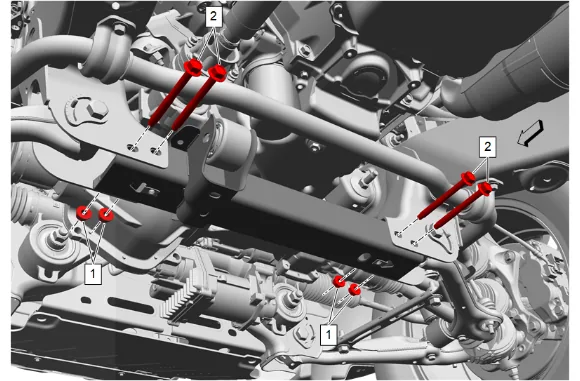
- Drivetrain and Front Suspension Frame Reinforcement Nut (1) » Remove [4x]
- Drivetrain and Front Suspension Frame Reinforcement Bolt (2) » Remove [4x]
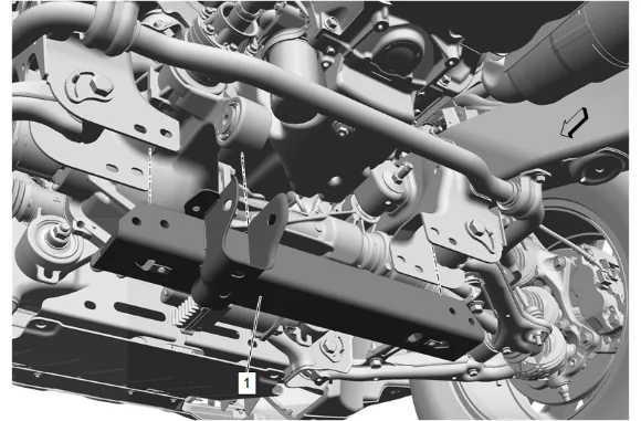
- Drivetrain and Front Suspension Frame Front Crossmember (1) » Remove
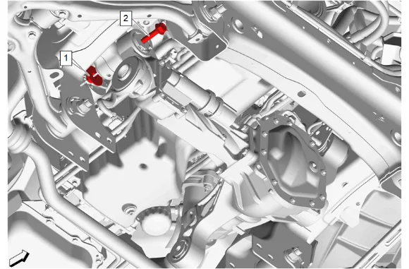
- Front Differential Carrier Bracket Nut (1) » Remove
- Front Differential Carrier Bolt (2) » Remove
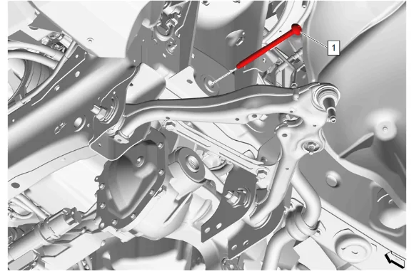
- Front Differential Carrier Bolt (1) » Remove
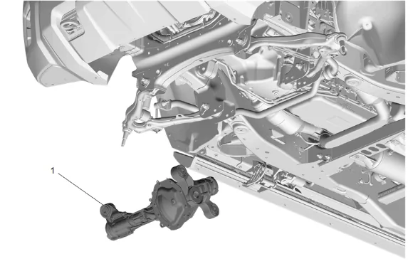
- Front Axle Vent Hose » Disconnect
- Front Axle (1) » Remove
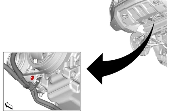
- Remove the transmission fluid auxiliary cooler pipe bracket nut (1).
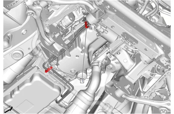
- Transmission Fluid Cooler Pipe Clip (1) » Open [2x]
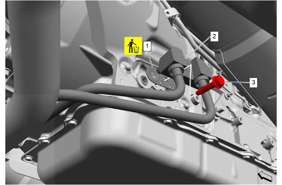
- Remove the transmission fluid cooler pipe connector bolt (3).
- Transmission Fluid Cooler Inlet and Outlet Pipe (2) @ Transmission » Remove
- Transmission Fluid Cooler Seal (1) » Remove and DISCARD
- Cap the fittings and plug the holes when removing the transmission fluid cooler pipes.
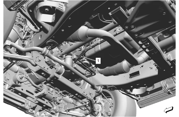
-
Maneuver the transmission cooler inlet and outlet pipe (1) as necessary to remove from under the vehicle. Installation Procedure
-
Maneuver the transmission cooler inlet and outlet pipe (1) as necessary to install.
-
Transmission Fluid Cooler Seal (1) » Install NEW
-
Transmission Fluid Cooler Inlet and Outlet Pipe (2) @ Transmission » Install
-
Install and tighten the transmission fluid cooler pipe connector bolt (3). Fastener Specifications
-
Transmission Fluid Cooler Pipe Clip (1) » Close [2x]
-
Install and tighten the transmission fluid auxiliary cooler pipe bracket nut (1). Fastener Specifications
-
Front Axle (1) » Install
-
Front Axle Vent Hose » Connect
-
Front Differential Carrier Bolt (1) » Install and tighten — Fastener Specifications
-
Front Differential Carrier Bolt (2) » Install
-
Front Differential Carrier Bracket Nut (1) » Install and tighten — Fastener Specifications
-
Drivetrain and Front Suspension Frame Front Crossmember (1) » Install
-
Drivetrain and Front Suspension Frame Reinforcement Bolt (2) » Install [4x]
-
Using the EN-45059-A Angle Meter, install and tighten the 4 drivetrain and front suspension frame reinforcement nuts (1). Fastener Specifications
- Front Differential Carrier Bolt (2) » Install NEW
- Front Differential Carrier Nut (1) » Install
- Using the EN-45059-A Angle Meter, tighten the front differential carrier nut (1). Fastener Specifications
-
Install the heater coolant pump and heater water auxiliary pump bracket (2) as assembly.
-
Heater Water Auxiliary Pump Bolt (1) » Install and tighten — Fastener Specifications
-
Electrical Connector @ Heater Coolant Pump (2) » Connect
-
Connect the front drive axle actuator electrical connector (1).
-
Reposition the harness and secure the 2 harness retainers (2).
-
If NEW threaded components are being installed, loosen the adhesive using a metal pick or similar tool before proceeding. If threaded components are reused, prepare the threaded components using the following steps: 23.1. Remove any loose cured adhesive from the external threads of the components using a lint free cloth. 23.2. Thread the cleaned components into the internal mating threads and remove to loosen trapped cured adhesive. 23.3. Apply thread locking adhesive to the external threads of the components. Adhesives, Fluids, Lubricants, and Sealers 23.4. Ensure there are no gaps in the thread locking adhesive once applied to the component.
-
Front Axle Propeller Shaft (1) » Reposition
-
Align the reference marks made between the front axle propeller shaft (1) and the front differential drive pinion gear yoke.
-
Front Axle Propeller Shaft Washer (3) » Install [3x]
-
Install the 6 front axle propeller shaft bolts (2) and tighten in a crisscross pattern. Fastener Specifications
-
Apply anti-corrosion wax to the frame shock tower. Anti-Corrosion Treatment and Repair
-
Front Shock Absorber (1) » Install
-
Front Shock Absorber Bolt (1) » Install and tighten [2x] — Fastener Specifications
-
Front Shock Absorber Nut (1) » Install and tighten [3x] — Fastener Specifications
-
Connect the air line and install the air line nut (1). Fastener Specifications
-
Reposition and install the chassis wiring harness bracket (1) to the frame shock tower.
-
Connect the electrical connector for the electronic suspension wheel front vertical accelerometer (1) and the front air shock harness electrical connector (2).
-
Front Wheelhouse Liner (1) » Install — Front Wheelhouse Liner Replacement
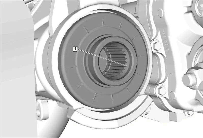
-
Remove any buildup from the front differential carrier output shaft lead in chamfer (1) using an abrasive pad and wipe clean with a shop cloth.
-
Front Wheel Drive Shaft Seal (2) » Install NEW
-
Front Wheel Drive Shaft Retaining Ring (1) » Install NEW
-
Apply a thin coating of grease to the splines of the front wheel drive half shaft and front differential carrier output shaft. Adhesives, Fluids, Lubricants, and Sealers
-
Install the front wheel drive half shaft (1) into the wheel hub.
-
Install the front wheel drive half shaft (1) into the front axle.
-
Ensure that the left front wheel drive half shaft (1) is fully seated in front differential carrier by pulling on the inner joint.
-
Support the steering knuckle with a suitable jack stand.
-
Front Upper Control Arm Ball Stud Nut (1) » Install and tighten — Fastener Specifications
-
Steering Linkage Outer Tie Rod Nut (1) » Install and tighten — Fastener Specifications
-
Install the electronic suspension wheel front vertical accelerometer (3) with the harnesses (1).
-
Electronic Suspension Rear Vertical Accelerometer Bolt (2) » Install and tighten — Fastener Specifications
-
Front Wheel Speed Sensor (2) » Install
-
Front Wheel Speed Sensor Bolt (1) » Install and tighten — Fastener Specifications
-
Front Wheel Speed Sensor Bracket (4) » Install
-
Front Wheel Speed Sensor Bracket Bolt (3) » Install and tighten — Fastener Specifications
-
If NEW threaded components are being installed, loosen the adhesive using a metal pick or similar tool before proceeding. If threaded components are reused, prepare the threaded components using the following steps: 52.1. Remove any loose cured adhesive from the external threads of the components using a lint free cloth. 52.2. Thread the cleaned components into the internal mating threads and remove to loosen trapped cured adhesive. 52.3. Apply thread locking adhesive to the external threads of the components. Adhesives, Fluids, Lubricants, and Sealers 52.4. Ensure there are no gaps in the thread locking adhesive once applied to the component.
-
Front Brake Caliper (1) » Install
-
Front Brake Caliper Bolt (2) » Install and tighten [2x] — Fastener Specifications
-
Front Brake Hose Bracket Bolt (1) » Install and tighten — Fastener Specifications
-
Front Disc Brake Pad Wear Sensor (1) @ Front Brake Caliper » Install
-
Remove any buildup from the front differential carrier output shaft lead in chamfer (1) using an abrasive pad and wipe clean with a shop cloth.
-
Front Wheel Drive Shaft Seal (2) » Install NEW
-
Front Wheel Drive Shaft Retaining Ring (1) » Install NEW
-
Apply a thin coating of grease to the splines of the front wheel drive half shaft and front differential carrier output shaft. Adhesives, Fluids, Lubricants, and Sealers
-
Install the front wheel drive half shaft (1) into the wheel hub.
-
Install the front wheel drive half shaft (1) into the front axle.
-
Ensure that the right front wheel drive half shaft (1) is fully seated in front differential carrier by pulling on the inner joint.
-
Support the steering knuckle with a suitable jack stand.
-
Front Upper Control Arm Ball Stud Nut (1) » Install and tighten — Fastener Specifications
-
Steering Linkage Outer Tie Rod Nut (1) » Install and tighten — Fastener Specifications
-
Install the harness (1) and the electronic suspension wheel front vertical accelerometer (3).
-
Electronic Suspension Rear Vertical Accelerometer Bolt (2) » Install and tighten — Fastener Specifications
-
Front Wheel Speed Sensor (2) » Install
-
Front Wheel Speed Sensor Bolt (1) » Install and tighten — Fastener Specifications
-
Front Wheel Speed Sensor Bracket (4) » Install
-
Front Wheel Speed Sensor Bracket Bolt (3) » Install and tighten — Fastener Specifications
-
If NEW threaded components are being installed, loosen the adhesive using a metal pick or similar tool before proceeding. If threaded components are reused, prepare the threaded components using the following steps: 73.1. Remove any loose cured adhesive from the external threads of the components using a lint free cloth. 73.2. Thread the cleaned components into the internal mating threads and remove to loosen trapped cured adhesive. 73.3. Apply thread locking adhesive to the external threads of the components. Adhesives, Fluids, Lubricants, and Sealers 73.4. Ensure there are no gaps in the thread locking adhesive once applied to the component.
-
Front Brake Caliper (1) » Install
-
Front Brake Caliper Bolt (2) » Install and tighten [2x] — Fastener Specifications
-
Front Brake Hose Bracket Bolt (1) » Install and tighten — Fastener Specifications
-
Have an assistant apply the brakes.
- Front Wheel Drive Shaft Nut (1) » Install NEW and tighten — Fastener Specifications
- Front Wheel Drive Shaft Nut (1) » Install NEW and tighten — Fastener Specifications
- Install the front tire and wheel assemblies. Tire and Wheel Removal and Installation
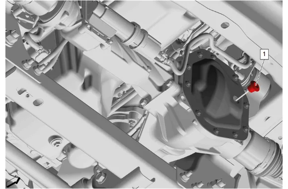
- Front Differential Carrier Oil Filler Plug (1) » Remove
- Inspect the gear lubricant level, it should be 16–22 mm (0.6-0.9 in) below the plug opening.
- If the level is low, add gear lubricant until the level is 16–22 mm (0.6-0.9 in) below the plug opening. Adhesives, Fluids, Lubricants, and Sealers
-
Front Differential Carrier Oil Filler Plug (1) » Install and tighten — Fastener Specifications
-
Front Stabilizer Shaft (1) » Install
-
Front Stabilizer Shaft Link Nut - Upper (1) @ Front Stabilizer Shaft » Install and tighten [2x] — Fastener Specifications
- Front Stabilizer Shaft Insulator (3) » Install [2x]
- Front Stabilizer Shaft Clamp (2) » Install [2x]
- If NEW threaded components are being installed, loosen the adhesive using a metal pick or similar tool before proceeding. If threaded components are reused, prepare the threaded components using the following steps: 89.1. Remove any loose cured adhesive from the external threads of the components using a lint free cloth. 89.2. Thread the cleaned components into the internal mating threads and remove to loosen trapped cured adhesive. 89.3. Apply thread locking adhesive to the external threads of the components. Adhesives, Fluids, Lubricants, and Sealers 89.4. Ensure there are no gaps in the thread locking adhesive once applied to the component.
- Front Stabilizer Shaft Bolt (1) » Install and tighten [4x] — Fastener Specifications
-
Underbody Skid Shield (3) » Install
-
Underbody Splash Shield Bolt (2) » Install and tighten [2x] — Fastener Specifications
-
Underbody Splash Shield (1) » Install
-
Underbody Splash Shield Bolt (1) » Install and tighten [4x] — Fastener Specifications
-
Underbody Splash Shield Bolt (2) » Install and tighten [4x] — Fastener Specifications
-
Lower the vehicle.
-
Install the condenser, fan, and radiator assembly (1). Condenser, Fan, and Radiator Assembly Removal and Installation
-
Connect the battery negative cable.
-
Check the transmission fluid level. Transmission Fluid Level and Condition Check
-
Turn service mode off.
-
With the vehicle off the hoist and on flat level ground, use the scan tool to reset trim heights. Trim Height Inspection