Differential Drive Pinion Gear Inner Bearing Replacement (G96)
Differential Drive Pinion Gear Inner Bearing Replacement (G96) Single Use Fasteners and Components Differential Carrier Front Bolt Differential Drive Pinion Gear Bearing Spacer Differential Drive Pinion Gear Nut Differential Drive Pinion Gear Seal Rear Axle Shaft Seal [2x] Special Tools DT-22912-B Bearing Remover DT-24433 Pinion Cone and Side Bearing Installer DT-3289-20 Holding Fixture DT-45124 Removal Bridge DT-50712 Bearing Cup Remover DT-52506 Pinion Flange Holder and Remover DT-52898 Pinion Bearing Cup Installer DT-52898-10 Pinion Bearing Cup Replacer Adapter DT-52902 Rear Drive Module Rotating Fixture DT-52902-5 Rear Drive Module Rotating Fixture Hardware DT-52903 Axle Flange Remover DT-52904 Input/Pinion Seal Installer DT-52905 Output Seal Installer - RH DT-52906 Output Seal Installer - LH/Motor DT-53030 Axis Snap Ring Installer GE-02619-A Slide Hammer w/Adapter GE-8092 Driver Handle Equivalent regional tools: Special Tools Removal Procedure
- Remove the spare tire.
- Raise and support the vehicle. Lifting and Jacking the Vehicle
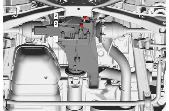
- Position a drain pan under the rear differential carrier (1).
- Rear Axle Housing Drain Plug (2) » Remove
- Rear Axle Housing Fill Plug (3) » Remove
- Clean the rear axle housing drain and fill plugs. Allow the fluid to completely drain.
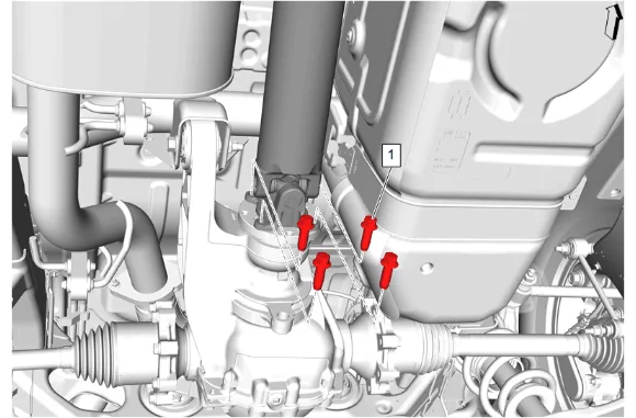
- Rear Propeller Shaft Bolt (1) » Remove [4x]
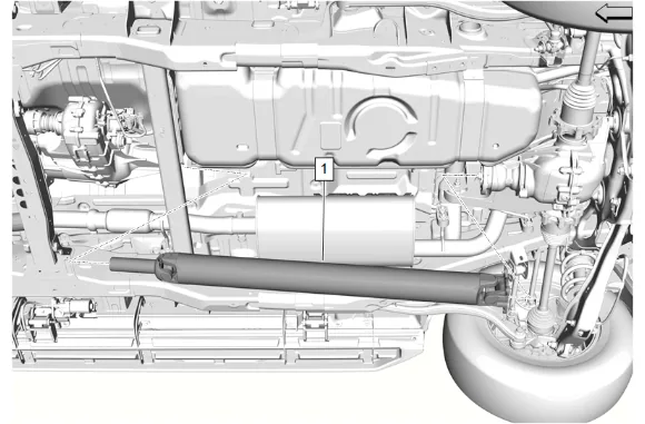
- Propeller Shaft (1) » Remove
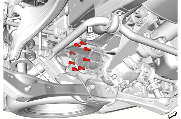
- Rear Wheel Drive Shaft Bolt (1) » Remove [8x]
- Reposition the right rear wheel drive shaft downwards.
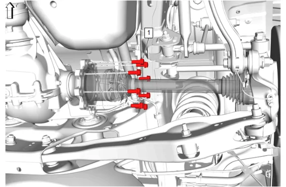
- Rear Wheel Drive Shaft Bolt (1) » Remove [8x]
- Reposition the left rear wheel drive shaft upwards.
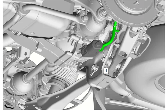
- Disconnect the limited slip differential clutch motor electrical connector (1).
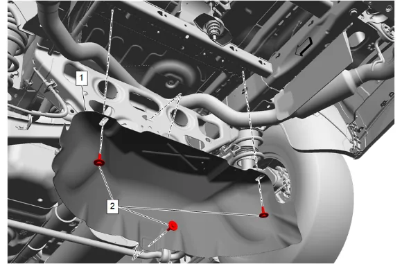
- {If equipped} with dual exhaust. 14.1. Spare Wheel Heat Shield Bolt (2) » Remove [3x] 14.2. Spare Wheel Heat Shield (1) » Remove
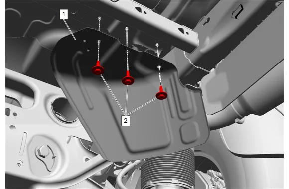
- {If equipped} with single exhaust. 15.1. Spare Wheel Heat Shield Bolt (2) » Remove [3x] 15.2. Spare Wheel Heat Shield (1) » Remove
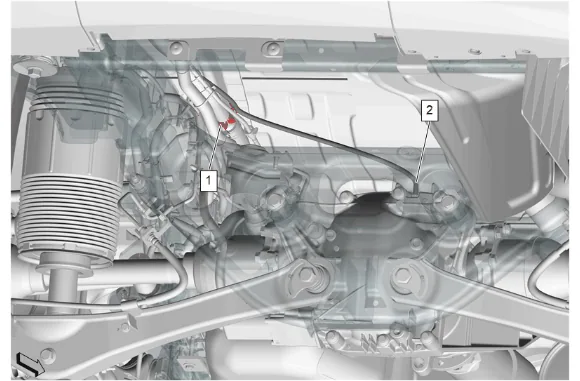
- Rear Axle Vent Hose (2) » Disconnect
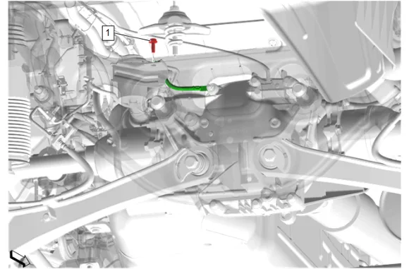
- Battery Cable Terminal Bolt (1) » Remove
- Differential Carrier Ground Cable » Reposition
- Support the rear differential carrier.
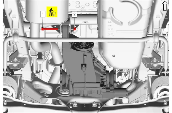
- Differential Carrier Nut (2) » Remove
- Differential Carrier Front Bolt (1) » Remove and DISCARD
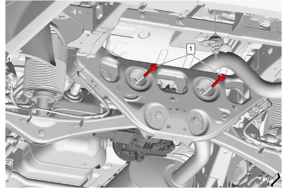
- Differential Carrier Rear Bolt (1) » Remove [2x]
- Lower the rear differential carrier.
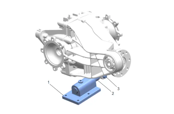
- Install the DT-52902 Rear Drive Module Rotating Fixture (2) to the rear axle housing using DT- 52902-5 Rear Drive Module Rotating Fixture Hardware (3) and attach to the DT-3289-20 Holding Fixture (1).
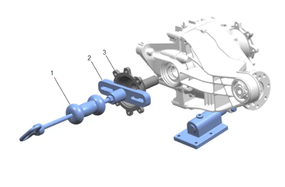
- Using DT-52903 Axle Flange Remover (2) and GE-02619-A Slide Hammer w/Adapter (1), Remove the rear axle shaft (3).
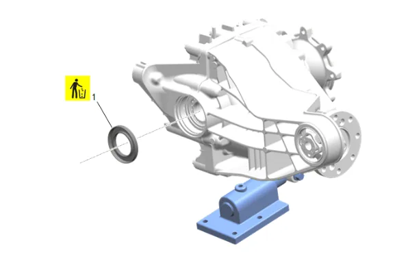
- Rear Axle Shaft Seal (1) » Remove and DISCARD
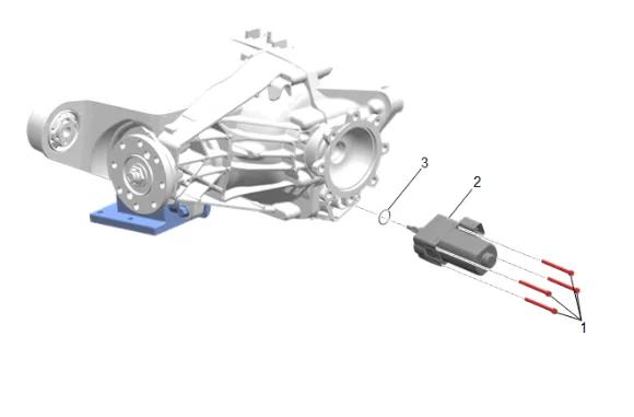
- Limited Slip Differential Clutch Motor Bolt (1) » Remove [4x]
- Limited Slip Differential Clutch Motor (2) » Remove
- Limited Slip Differential Clutch Motor Seal (3) » Remove
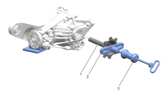
- Using DT-52903 Axle Flange Remover (2) and GE-02619-A Slide Hammer w/Adapter (3), Remove the rear axle shaft (1).
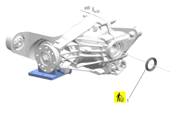
- Rear Axle Shaft Seal (1) » Remove and DISCARD
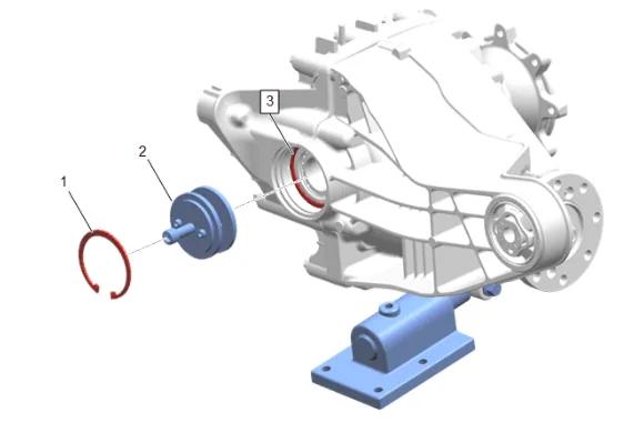
- Using DT-53030 Axis Snap Ring Installer (2) and a secondary differential bearing retaining ring (1) apply moderate pressure to free the differential bearing retaining ring (3).
- Remove the secondary differential bearing retaining ring (1) and DT-53030 Axis Snap Ring Installer (2).
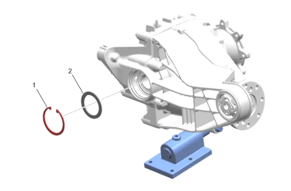
- Differential Bearing Retaining Ring (1) » Remove
- Differential Bearing Shim (2) » Remove
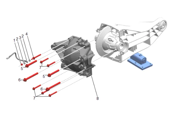
- Differential Carrier Nut (1) » Remove
- Remove the 2 differential carrier bracket washers (2) and the differential carrier ground cable (3).
- Battery Negative Cable Ground Stud (4) » Remove
- Differential Carrier Cover Bolt (7) » Remove [5x]
- Rear Axle Housing Cover Bolt (5) » Remove [2x]
- Rear Axle Housing Cover Bolt (6) » Remove [2x]
- Rear Axle Housing (8) » Remove
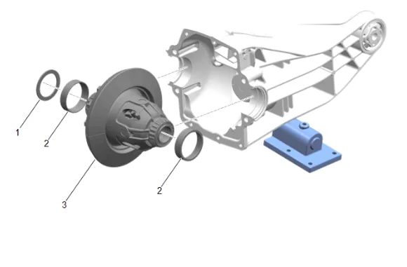
- Remove the differential (3), bearing races (2), and shim (1).
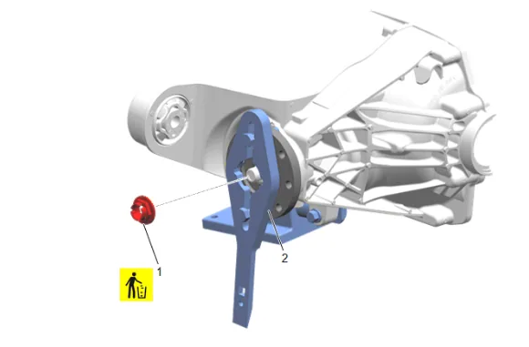
- Using DT-52506 Pinion Flange Holder and Remover (2), Remove and DISCARD the differential drive pinion gear nut (1).
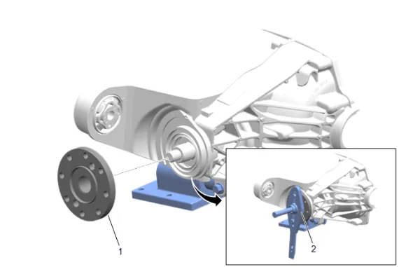
- Using DT-52506 Pinion Flange Holder and Remover (2), Remove the differential drive pinion gear yoke (1).
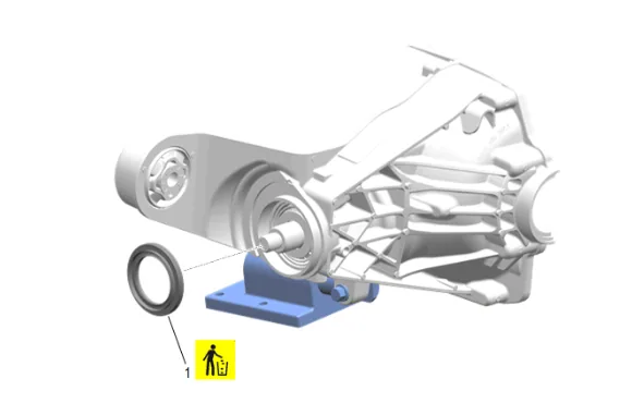
- Differential Drive Pinion Gear Seal (1) » Remove and DISCARD
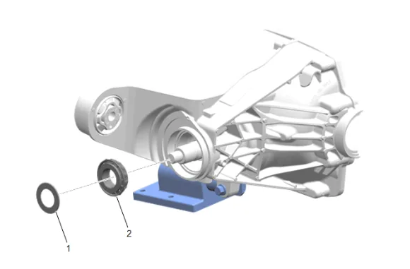
- Differential Drive Pinion Gear Washer (1) » Remove
- Differential Drive Pinion Gear Outer Bearing (2) » Remove
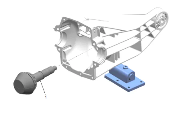
- Differential Drive Pinion Gear (1) » Remove
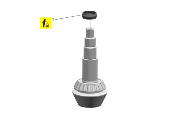
- Differential Drive Pinion Gear Bearing Spacer (1) » Remove and DISCARD
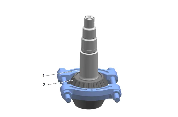
- Using DT-22912-B Bearing Remover (1), Remove the differential drive pinion gear inner bearing (2).
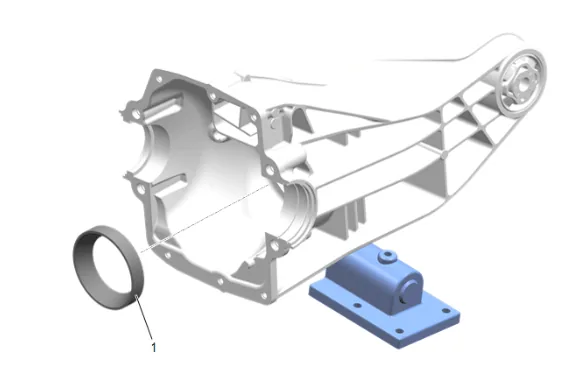
- Using a brass drift and hammer, Remove the differential drive pinion inner bearing cup (1).
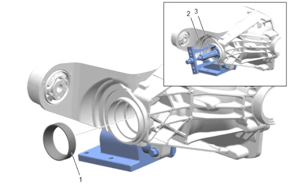
- Using DT-45124 Removal Bridge (2) and DT-50712 Bearing Cup Remover (3), Remove the differential drive pinion outer bearing cup (1). Cleaning and Inspection Procedure - Required
- Clean any debris and material from the axle housing.
- Clean the rear axle housing chip collector magnet.
- Inspect the axle housing for damage and burrs, if any damage or burrs are found replacement of the axle housing would be necessary.
- Clean off the old sealant from the rear axle housing and rear axle housing cover using Acetone, followed by Isopropyl Alcohol. Installation Procedure
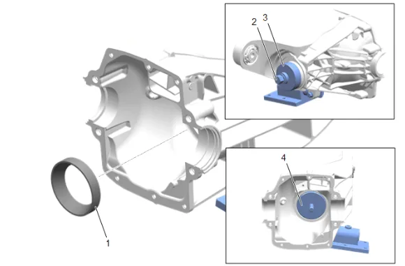
- Using DT-52898-4 (3), DT-52898-10 (4), and DT-52898-5 (2), Install the differential drive pinion inner bearing cup (1).
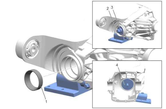
- Using DT-52898-10 (4), DT-52898-3 (3), and DT-52898-5 (2), Install the differential drive pinion outer bearing cup (1).
-
Measure the thickness needed for the differential drive pinion bearing shims, refer to Pinion Depth Adjustment.
-
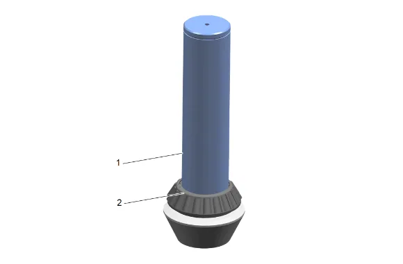
Using DT-24433 Pinion Cone and Side Bearing Installer (1), Install NEW differential drive pinion gear inner bearing (2) onto the differential drive pinion gear with the appropriate shim.
-
Differential Drive Pinion Gear Bearing Spacer (1) » Install NEW
- Differential Drive Pinion Gear Outer Bearing (2) » Install
- Differential Drive Pinion Gear Washer (1) » Install
-
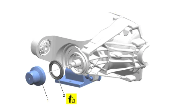
Using DT-52904 Input/Pinion Seal Installer (1), Install NEW differential drive pinion gear seal (2).
-
Differential Drive Pinion Gear (1) » Install
-
Apply sealant to the pinion yoke splines. Adhesives, Fluids, Lubricants, and Sealers
-
Apply grease to the pinion seal where it will contact the pinion gear yoke slinger. Adhesives, Fluids, Lubricants, and Sealers
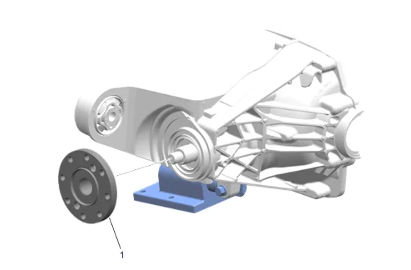
- Differential Drive Pinion Gear Yoke (1) » Install
- Using DT-52506 Pinion Flange Holder and Remover (2), Install NEW and tighten the differential drive pinion gear nut (1). Fastener Specifications
- Measure the thickness needed for the differential bearing shims, refer to Differential Carrier Bearing Preload Adjustment.
- Measure and adjust the backlash, refer to Backlash Adjustment.
- Install the differential (3), bearing races (2), and shim (1).
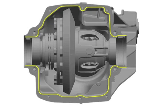
- Apply a 2 mm (0.08 in) wide bead of sealant to the rear axle housing per the template above. Adhesives, Fluids, Lubricants, and Sealers The bead should be 2 mm (0.08 in) high and 2 mm (0.079 in) from the chamfer.
-
Rear Axle Housing (8) » Install
-
If NEW threaded components are being installed, loosen the adhesive using a metal pick or similar tool before proceeding. If threaded components are reused, prepare the threaded components using the following steps: 19.1. Remove any loose cured adhesive from the external threads of the components using a lint free cloth. 19.2. Thread the cleaned components into the internal mating threads and remove to loosen trapped cured adhesive. 19.3. Remove loose debris from internal and external threads using compressed air. 19.4. Apply liquid thread locking adhesive in a strip along half of the length of the external threads, starting at the tip, just prior to installation. Adhesives, Fluids, Lubricants, and Sealers
-
Rear Axle Housing Cover Bolt (6) » Install and tighten [2x] — Fastener Specifications
-
Rear Axle Housing Cover Bolt (5) » Install and tighten [2x] — Fastener Specifications
-
Differential Carrier Cover Bolt (7) » Install and tighten [5x] — Fastener Specifications
-
Battery Negative Cable Ground Stud (4) » Install and tighten — Fastener Specifications
-
Install the 2 differential carrier bracket washers (2) and the differential carrier ground cable (3) match the removal position of the cable.
-
Differential Carrier Nut (1) » Install and tighten — Fastener Specifications
-
Differential Bearing Shim (2) » Install
-
Differential Bearing Retaining Ring (1) » Install
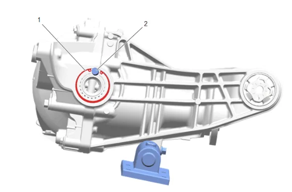
-
Using DT-53030 Axis Snap Ring Installer (2) verify the differential bearing retaining ring (1) is fully seated. There should be a minimum 16.55 mm (0.652 in) gap between the ends of the differential bearing retaining ring (1).
-
If the differential bearing retaining ring is not fully seated, use DT-53030 Axis Snap Ring Installer (2) and a secondary differential bearing retaining ring (1) to apply moderate pressure to the differential bearing retaining ring (3) to preload the differential bearings allowing the differential bearing retaining ring to seat.
-
If necessary, remove the secondary differential bearing retaining ring (1) and DT-53030 Axis Snap Ring Installer (2).
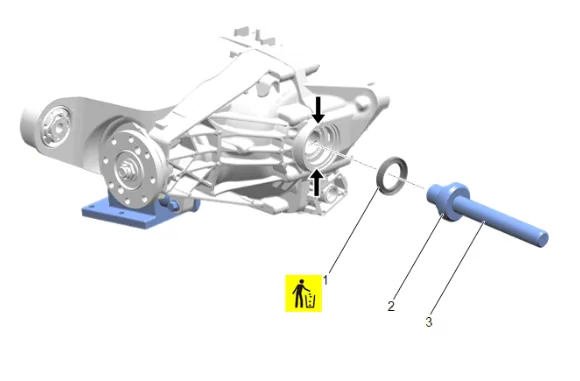
- Remove (wipe out) excess sealant from the seal bore and deflector groove at the locations indicated by arrows, before installing the rear axle shaft seal.
- Using the DT-52906 Output Seal Installer - LH/Motor (2) and GE-8092 Driver Handle (3), Install NEW rear axle shaft seal (1).
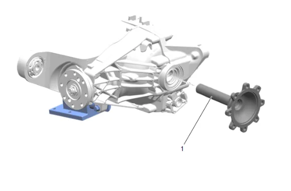
-
Rear Axle Shaft (1) » Install
-
Limited Slip Differential Clutch Motor Seal (3) » Install
-
Limited Slip Differential Clutch Motor (2) » Install
-
Limited Slip Differential Clutch Motor Bolt (1) » Install and tighten [4x] — Fastener Specifications
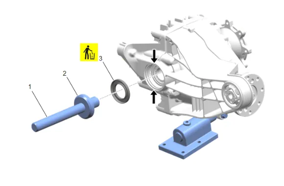
- Remove (wipe out) excess sealant from the seal bore and deflector groove at the locations indicated by arrows, before installing the rear axle shaft seal.
- Using the DT-52905 Output Seal Installer - RH (2) and GE-8092 Driver Handle (1), Install NEW rear axle shaft seal (3).
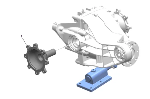
-
Rear Axle Shaft (1) » Install
-
Remove the DT-52902 Rear Drive Module Rotating Fixture (2).
-
Raise the differential carrier.
-
Differential Carrier Rear Bolt (1) » Install and tighten [2x] — Fastener Specifications
- Differential Carrier Front Bolt (1) » Install NEW
- Differential Carrier Nut (2) » Install and tighten — Fastener Specifications
- Remove support from the rear differential carrier.
-
Differential Carrier Ground Cable » Reposition
-
Battery Cable Terminal Bolt (1) » Install and tighten — Fastener Specifications
-
Rear Axle Vent Hose (2) » Connect
-
{If equipped} with dual exhaust. 49.1. Spare Wheel Heat Shield (1) » Install 49.2. Spare Wheel Heat Shield Bolt (2) » Install and tighten [3x] — Fastener Specifications
-
{If equipped} with single exhaust. 50.1. Spare Wheel Heat Shield (1) » Install 50.2. Spare Wheel Heat Shield Bolt (2) » Install and tighten [3x] — Fastener Specifications
-
Connect the limited slip differential clutch motor electrical connector (1).
-
If NEW threaded components are being installed, loosen the adhesive using a metal pick or similar tool before proceeding. If threaded components are reused, prepare the threaded components using the following steps: 52.1. Remove any loose cured adhesive from the external threads of the components using a lint free cloth. 52.2. Thread the cleaned components into the internal mating threads and remove to loosen trapped cured adhesive. 52.3. Apply thread locking adhesive to the external threads of the components. Adhesives, Fluids, Lubricants, and Sealers 52.4. Ensure there are no gaps in the thread locking adhesive once applied to the component.
-
Reposition the right rear wheel drive shaft.
-
Rear Wheel Drive Shaft Bolt (1) » Install and tighten [8x] — Fastener Specifications
-
If NEW threaded components are being installed, loosen the adhesive using a metal pick or similar tool before proceeding. If threaded components are reused, prepare the threaded components using the following steps: 55.1. Remove any loose cured adhesive from the external threads of the components using a lint free cloth. 55.2. Thread the cleaned components into the internal mating threads and remove to loosen trapped cured adhesive. 55.3. Apply thread locking adhesive to the external threads of the components. Adhesives, Fluids, Lubricants, and Sealers 55.4. Ensure there are no gaps in the thread locking adhesive once applied to the component.
-
Reposition the left rear wheel drive shaft.
-
Rear Wheel Drive Shaft Bolt (1) » Install and tighten [8x] — Fastener Specifications
-
Propeller Shaft (1) » Install
-
If NEW threaded components are being installed, loosen the adhesive using a metal pick or similar tool before proceeding. If threaded components are reused, prepare the threaded components using the following steps: 59.1. Remove any loose cured adhesive from the external threads of the components using a lint free cloth. 59.2. Thread the cleaned components into the internal mating threads and remove to loosen trapped cured adhesive. 59.3. Apply thread locking adhesive to the external threads of the components. Adhesives, Fluids, Lubricants, and Sealers 59.4. Ensure there are no gaps in the thread locking adhesive once applied to the component.
-
Rear Propeller Shaft Bolt (1) » Install and tighten [4x] — Fastener Specifications
- Rear Axle Housing Drain Plug (2) Install and tighten — Fastener Specifications
- Fill the rear differential carrier with the appropriate amount and type of axle lubricant: Adhesives, Fluids, Lubricants, and Sealers Approximate Fluid Capacities
- The axle lubricant level should be 1 - 2 mm (0.039 - 0.079 in) below the fill plug opening.
- Rear Axle Housing Fill Plug (3) » Install and tighten — Fastener Specifications
- Remove the support and lower the vehicle.
- Install the spare tire.