Drive Range, Sixth Gear (Hydraulic Circuits)
As the vehicle speed increases, the transmission control module (TCM) receives input signals from the automatic transmission input and output speed sensors, throttle position sensor and other vehicle sensors to determine the precise moment to energize or turn on. Shift solenoid valve D is commanded ON and Shift solenoid valve C is commanded OFF. 1-2-3-4-6-7-8-10 Reverse Clutch Applies 1-2-3-4-6-7-8-10 Reverse Clutch Regulator Valve Shift solenoid valve D is energized and applying pressure against the 1-2-3-4-6-7-8-10 reverse clutch regulator valve allowing LINE (2) fluid to enter the 1234678-10R CLUTCH (30) fluid circuit. 1234678-10R CLUTCH (30) fluid is also directed through orifice #21 into the 1234678-10R CLUTCH FEEDBACK (31) fluid passage to the 1-2-3-4-6-7-8-10 reverse clutch regulator valve. 1-2-3-4-6-7-8-10 Reverse Clutch Assembly 1234678-10R CLUTCH (30) fluid is directed through orifice # 24 into the 1-2-3-4-6-7-8-10 reverse clutch assembly. 1234678- 10R CLUTCH (30) fluid moves the piston against spring force to apply holding of the 1-2-3-4-6-7-8-10 reverse clutch plates. 2-3-4-5-7-9-10 Clutch Releases 2-3-4-5-7-9-10 Clutch Regulator Valve Shift solenoid valve C is signaled off allowing 234579-10 CLUTCH (27) fluid to exhaust through orifice #15 and into the 234579- 10 CLUTCH EXHAUST (29) fluid circuit. 234579-10 CLUTCH EXHAUST (29) fluid is directed through the DRIVE DEFAULT (17) fluid circuit to the exhaust backfill blow off valve through the EXHAUST BACKFILL (39) fluid circuit. Torque Converter Clutch (TCC) Applies Torque Converter Clutch (TCC) Control Solenoid Valve The TCC control solenoid valve is commanded ON, allowing SECONDARY LINE (3) fluid to enter the VFS-TCC (10) fluid circuit. VFS-TCC (10) fluid is directed thru orifice #36 to the VFS TCC damper and thru orifice #37 to the TCC regulator control valve. TCC Regulator Control Valve VFS-TCC (10) fluid moves the TCC regulator control valve against TCC regulator control valve spring force, allowing PUMP OUT (3) fluid to pass through the valve into the TCC APPLY (7) fluid circuit and apply the torque converter clutch. TCC release (6) fluid passes through the TCC regulator control valve and is exhausted. Drive Range, Sixth Gear
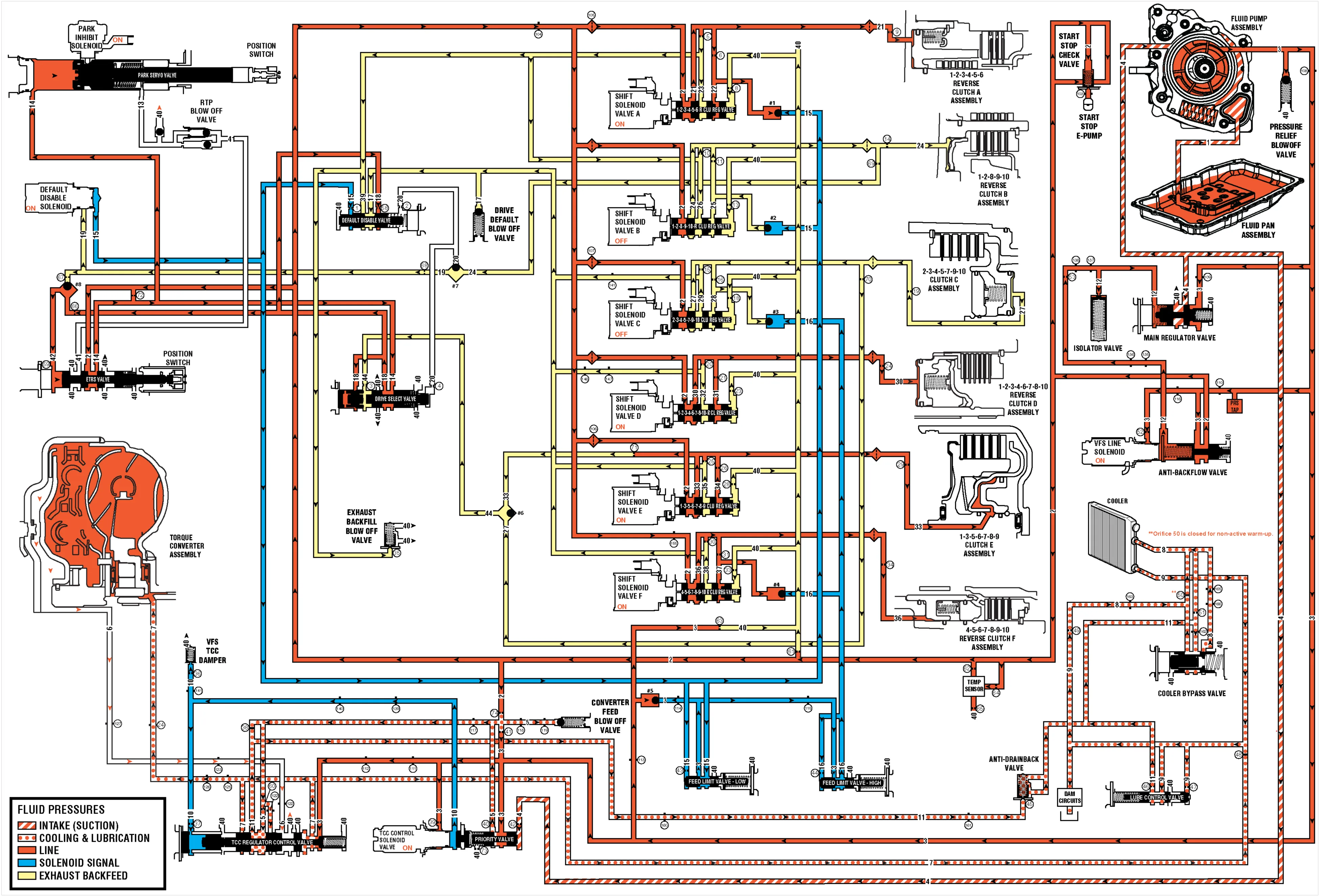
(1) Suction (2) Line (3) Pump Out (4) Decrease (5) Converter Feed (6) TCC Release (7) TCC Apply (8) Cooler Feed (9) Lube (10) VFS-TCC (11) Converter Return (12) VFS Line (13) Park On (14) Park Off (15) Feed Limit – Low (16) Feed Limit – High (17) Drive Default (18) Drive Latch (19) ON/OFF Signal (20) On/Off 1289-10 Reverse Clutch (21) 123456 Reverse Clutch (22) 123456 Reverse Clutch Feedback (23) 123456 Reverse Clutch Exhaust (24) 1289-10 Reverse Clutch (25) 1289-10 Reverse Clutch Feedback (26) 1289-10 Reverse Clutch Exhaust (27) 234579-10 Clutch (28) 234579-10 Clutch Feedback (29) 234579-10 Clutch Exhaust (30) 1234678-10 Reverse Clutch (31) 1234678-10 Reverse Clutch Feedback (32) 1234678-10 Reverse Clutch Exhaust (33) 1356789 Clutch (34) 1356789 Clutch Feedback (35) 1356789 Clutch Exhaust (36) 456789-10 Reverse Clutch (37) 456789-10 Reverse Clutch Feedback (38) 456789-10 Reverse Clutch Exhaust (39) Exhaust Backfill (40) Exhaust (41) Return to Park (42) On/Off Drive Latch (44) 234579-10/1356789 Clutch