Differential Ring and Pinion Gear Replacement (G86)
Single Use Fasteners and Components Differential Carrier Front Bolt Differential Drive Pinion Gear Nut Differential Drive Pinion Gear Seal Differential Ring Gear Bolt [12x] Rear Axle Shaft Seal [2x] Special Tools DT-22888-20A Universal Two Jaw Puller DT-24384-A Oil Seal Installer DT-3289-20 Holding Fixture DT-36597 Side Bearing Puller Pilot - 9.25 Inch DT-44412 Pinion Bearing Installer DT-52506 Pinion Flange Holder and Remover DT-52896 Pinion Seal and Side Bearing Installer DT-52898 Pinion Bearing Cup Installer DT-52900 Rear Cover Spreader Assembly DT-52902 Rear Drive Module Rotating Fixture DT-52903 Axle Flange Remover DT-5590 Bearing and Seal Driver GE-02619-A Slide Hammer w/Adapter Equivalent regional tools: Special Tools Removal Procedure
- Remove the spare tire.
- Raise and support the vehicle. Lifting and Jacking the Vehicle
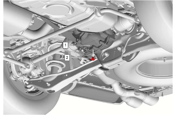
- Position a drain pan under the rear differential carrier (1).
- Rear Axle Housing Drain Plug (2) » Remove
- Clean the rear axle housing drain plug. Allow the fluid to completely drain.
- Rear Axle Housing Drain Plug (2) » Install and tighten — Fastener Specifications
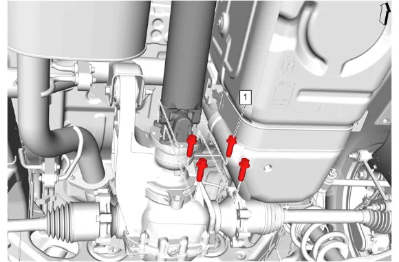
- Rear Propeller Shaft Bolt (1) » Remove [4x]
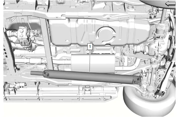
- Propeller Shaft (1) » Remove
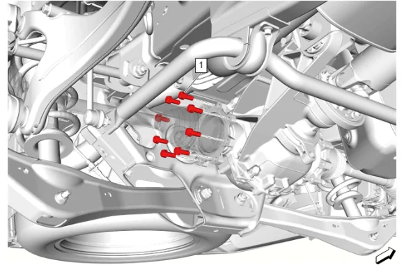
- Rear Wheel Drive Shaft Bolt (1) » Remove [8x]
- Reposition the right rear wheel drive shaft downward.
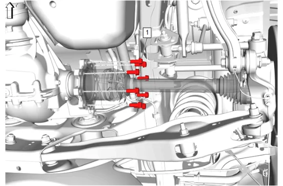
- Rear Wheel Drive Shaft Bolt (1) » Remove [8x]
- Reposition the left rear wheel drive shaft downward.
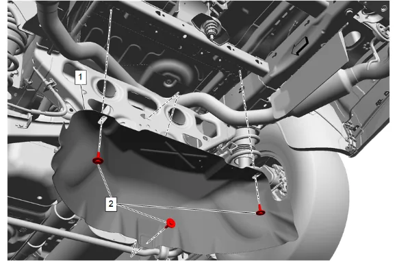
- {If equipped} with dual exhaust. 13.1. Spare Wheel Heat Shield Bolt (2) » Remove [3x] 13.2. Spare Wheel Heat Shield (1) » Remove
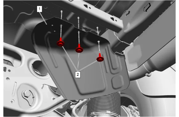
- {If equipped} with single exhaust. 14.1. Spare Wheel Heat Shield Bolt (2) » Remove [3x] 14.2. Spare Wheel Heat Shield (1) » Remove
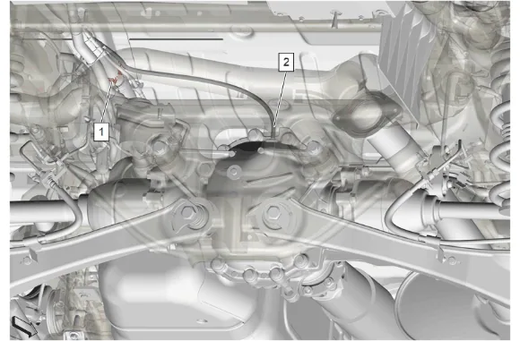
- Rear Axle Vent Hose (2) » Disconnect
- Support the rear differential carrier.
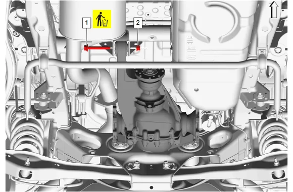
- Differential Carrier Nut (2) » Remove
- Differential Carrier Front Bolt (1) » Remove and DISCARD
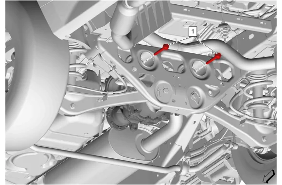
- Differential Carrier Rear Bolt (1) » Remove [2x]
- Lower the rear differential carrier.
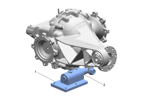
- Install the DT-52902 Rear Drive Module Rotating Fixture (2) to the rear axle housing and attach to the DT-3289-20 Holding Fixture (1).
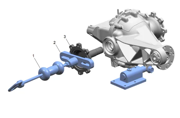
- Using DT-52903 Axle Flange Remover (2) and GE-02619-A Slide Hammer w/Adapter (1), Remove the rear axle shaft (3).
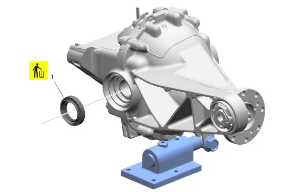
- Rear Axle Shaft Seal (1) » Remove and DISCARD
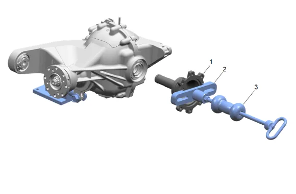
- Using DT-52903 Axle Flange Remover (2) and GE-02619-A Slide Hammer w/Adapter (3), Remove the rear axle shaft (1).
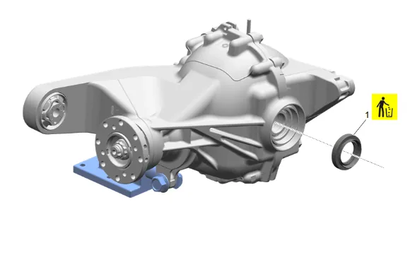
- Rear Axle Shaft Seal (1) » Remove and DISCARD
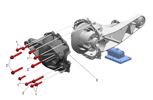
- Rear Axle Housing Cover Bolt (1) » Remove [8x]
- Rear Axle Housing Cover Bolt (2) » Remove [4x]
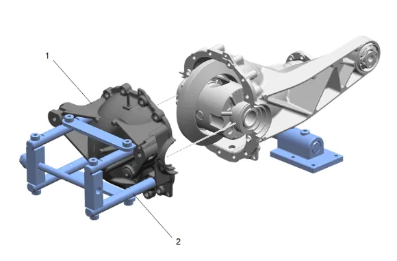
- Using the DT-52900 Rear Cover Spreader Assembly (2), Remove the rear axle housing (1).
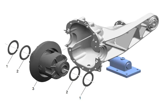
- Remove the differential (3), spacers (2), and shims (1).
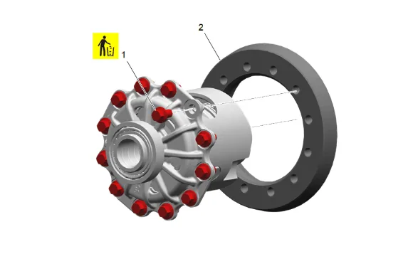
- Differential Ring Gear Bolt (1) » Remove and DISCARD [12x]
- Differential Ring Gear (2) » Remove
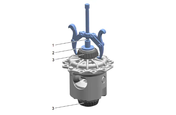
- Using DT-22888-20A Universal Two Jaw Puller (1) and DT-36597 Side Bearing Puller Pilot - 9.25 Inch (2), Remove the 2 differential bearings (3).
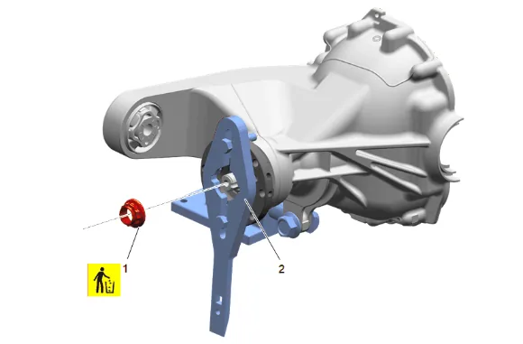
- Using DT-52506 Pinion Flange Holder and Remover (2), Remove and DISCARD the differential drive pinion gear nut (1).
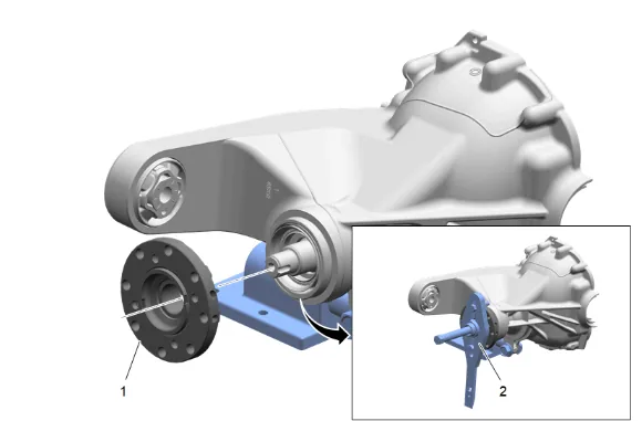
- Using DT-52506 Pinion Flange Holder and Remover (2), Remove the differential drive pinion gear yoke (1).
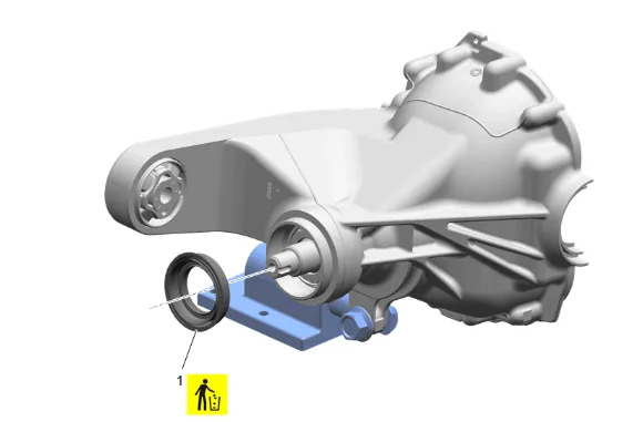
- Differential Drive Pinion Gear Seal (1) » Remove and DISCARD
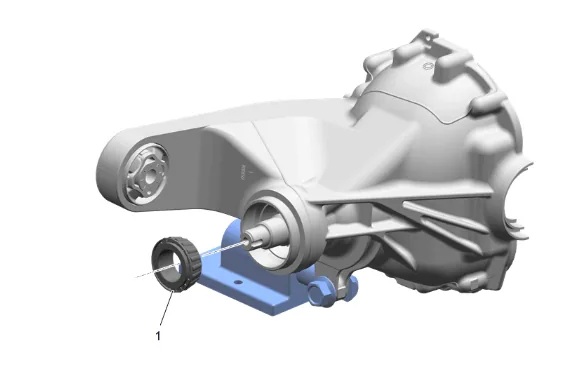
- Differential Drive Pinion Gear Outer Bearing (1) » Remove
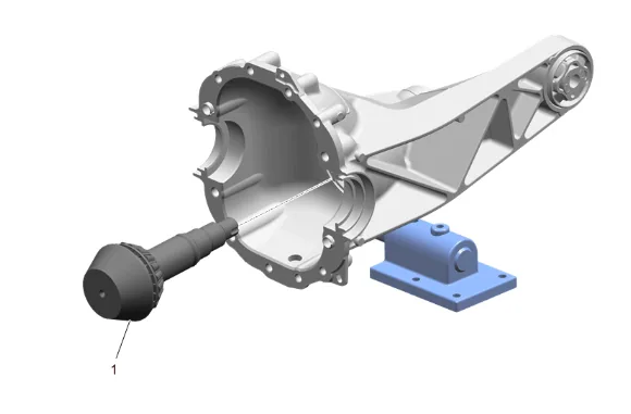
- Differential Drive Pinion Gear (1) » Remove
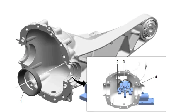
- Using DT-52898-7 (2), DT-52898-6 (3), and DT-22888-20A Universal Two Jaw Puller (4), Remove the differential drive pinion inner bearing cup (1). Assemble the tools with DT-52898- 6 rotated so that the flat sides are towards the jaws, this allows the jaws to compress and fit through the center of the bearing cup. Once the jaws are through the bearing cup rotate DT- 52898-6 so that it is inline with the jaws, this keep the jaws firmly hooked into the bearing cup. If necessary hold the upper portion of the jaws with a suitable tool to keep the jaws in place during the removal of the bearing cup.
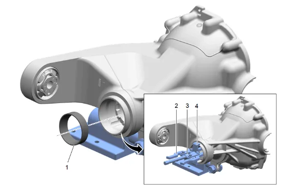
- Using DT-52898-8 (4), DT-52898-7 (2), and DT-22888-20A Universal Two Jaw Puller (3), Remove the differential drive pinion outer bearing cup (1). If necessary hold the upper portion of the jaws with a suitable tool to keep the jaws in place during the removal of the bearing cup. Cleaning and Inspection Procedure - Required
- Clean any debris and material from the axle housing.
- Inspect the axle housing for damage and burrs, if any damage or burrs are found replacement of the axle housing would be necessary.
- Clean off the old sealant from the rear axle housing and rear axle housing cover using Acetone, followed by Isopropyl Alcohol. Installation Procedure
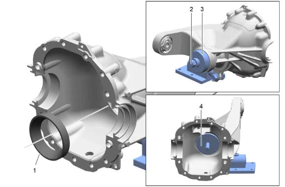
- Using DT-52898-4 (3), DT-52898-1 (4), and DT-52898-5 (2), Install the differential drive pinion inner bearing cup (1).
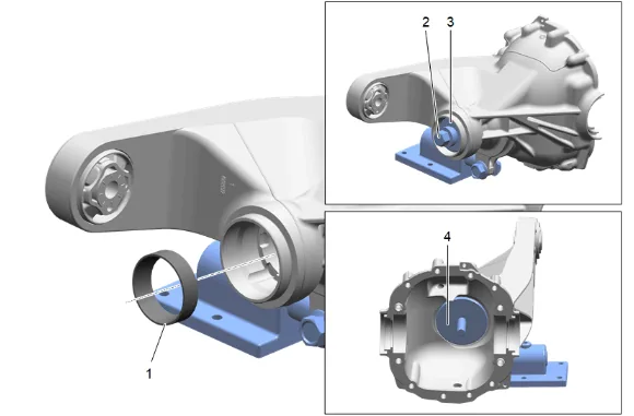
- {If 9.5 inch RDM} Using DT-52898-1 (4), DT-52898-2 (3), and DT-52898-5 (2), Install the differential drive pinion outer bearing cup (1).
- {If 9.76 inch RDM} Using DT-52898-1 (4), DT-52898-3 (3), and DT-52898-5 (2), Install the differential drive pinion outer bearing cup (1).
- Measure the thickness needed for the differential drive pinion bearing shims, refer to Pinion Depth Adjustment.
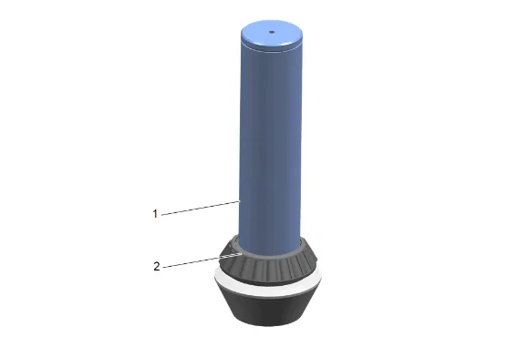
- Using DT-44412 Pinion Bearing Installer (1), Install NEW differential drive pinion gear inner bearing (2) onto the differential drive pinion gear with the appropriate shim.
-
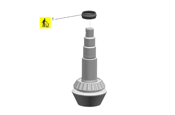
Differential Drive Pinion Gear Bearing Spacer (1) » Install NEW
-
Differential Drive Pinion Gear Outer Bearing (1) » Install
-
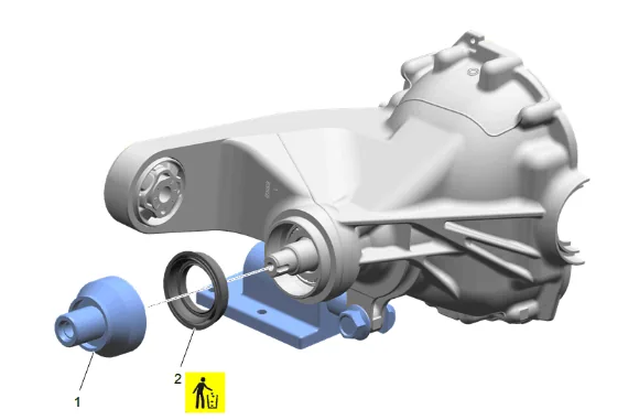
Using DT-52896 Pinion Seal and Side Bearing Installer (1) , Install NEW differential drive pinion gear seal (2).
-
Differential Drive Pinion Gear (1) » Install
-
Apply sealant to the pinion yoke splines. Adhesives, Fluids, Lubricants, and Sealers
-
Apply grease to the pinion seal where it will contact the pinion gear yoke slinger. Adhesives, Fluids, Lubricants, and Sealers
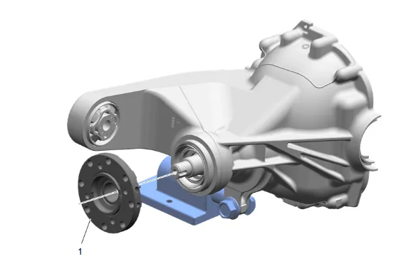
- Differential Drive Pinion Gear Yoke (1) » Install
-
Using DT-52506 Pinion Flange Holder and Remover (2), Install NEW and tighten the differential drive pinion gear nut (1). Fastener Specifications
-
Differential Ring Gear (2) » Install
- Differential Ring Gear Bolt (1) » Install NEW and tighten [12x] — Fastener Specifications
-
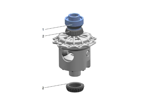
Using DT-52896 Pinion Seal and Side Bearing Installer (1) and a shop press, Install NEW 2 differential bearing (2).
-
Measure the thickness needed for the differential bearing shims, refer to Differential Carrier Bearing Preload Adjustment
-
Measure and adjust the backlash, refer to Backlash Adjustment.
-
Place the spacers (2) and shims (1) on the ends of the differential (3) and set the differential assembly into the rear axle housing.
- Install the differential (3), spacers (2), and shims (1).
-
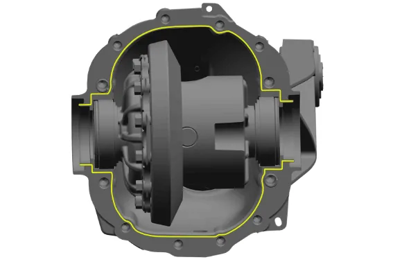
Apply a 4 mm (0.157 in) wide bead of sealant to the rear axle housing per the template above. Adhesives, Fluids, Lubricants, and Sealers The bead should be 2 mm (0.079 in) high and 2 mm (0.079 in) from the chamfer.
-
Using the DT-52900 Rear Cover Spreader Assembly (2), Install the rear axle housing (1).
-
If NEW threaded components are being installed, loosen the adhesive using a metal pick or similar tool before proceeding. If threaded components are reused, prepare the threaded components using the following steps: 23.1. Remove any loose cured adhesive from the external threads of the components using a lint free cloth. 23.2. Thread the cleaned components into the internal mating threads and remove to loosen trapped cured adhesive. 23.3. Apply thread locking adhesive to the external threads of the components. Adhesives, Fluids, Lubricants, and Sealers 23.4. Ensure there are no gaps in the thread locking adhesive once applied to the component.
-
Rear Axle Housing Cover Bolt (2) » Install and tighten [4x] — Fastener Specifications
-
Rear Axle Housing Cover Bolt (1) » Install and tighten [8x] — Fastener Specifications
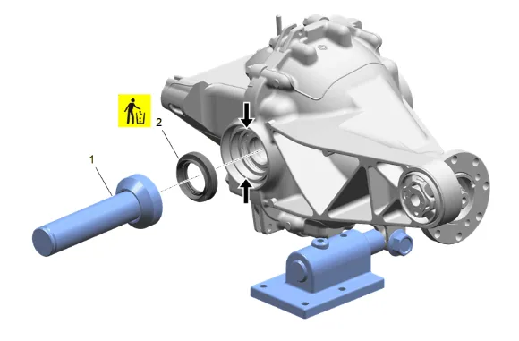
- Remove (wipe out) excess sealant from the seal bore and deflector groove at the locations indicated by arrows, before installing the rear axle shaft seal.
- Using the DT-24384-A Oil Seal Installer and DT-5590 Bearing and Seal Driver (1), Install NEW rear axle shaft seal (2).
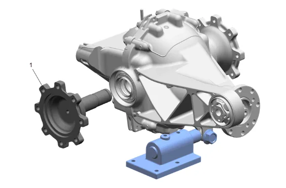
- Rear Axle Shaft (1) » Install
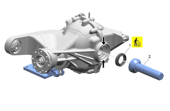
- Remove (wipe out) excess sealant from the seal bore and deflector groove at the locations indicated by arrows, before installing the rear axle shaft seal.
- Using the DT-24384-A Oil Seal Installer and DT-5590 Bearing and Seal Driver (2), Install NEW rear axle shaft seal (1).
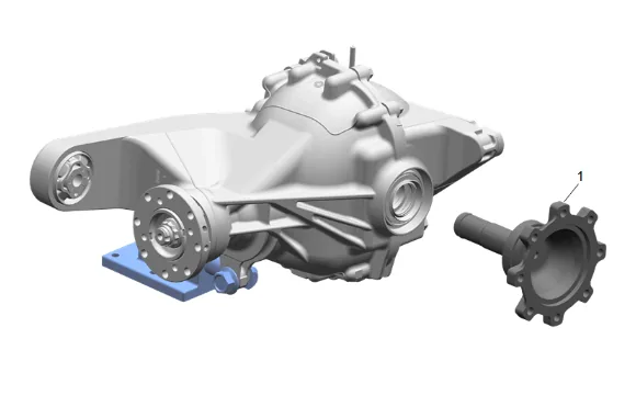
-
Rear Axle Shaft (1) » Install
-
Remove the DT-52902 Rear Drive Module Rotating Fixture (2).
-
Raise the differential carrier.
-
Differential Carrier Rear Bolt (1) » Install and tighten [2x] — Fastener Specifications
-
Differential Carrier Front Bolt (1) » Install NEW
-
Differential Carrier Nut (2) » Install and tighten — Fastener Specifications
-
Remove support from the rear differential carrier.
-
Rear Axle Vent Hose (2) » Connect
-
{If equipped} with dual exhaust. 39.1. Spare Wheel Heat Shield (1) » Install 39.2. Spare Wheel Heat Shield Bolt (2) » Install and tighten [3x] — Fastener Specifications
-
{If equipped} with single exhaust. 40.1. Spare Wheel Heat Shield (1) » Install 40.2. Spare Wheel Heat Shield Bolt (2) » Install and tighten [3x] — Fastener Specifications
-
If NEW threaded components are being installed, loosen the adhesive using a metal pick or similar tool before proceeding. If threaded components are reused, prepare the threaded components using the following steps: 41.1. Remove any loose cured adhesive from the external threads of the components using a lint free cloth. 41.2. Thread the cleaned components into the internal mating threads and remove to loosen trapped cured adhesive. 41.3. Apply thread locking adhesive to the external threads of the components. Adhesives, Fluids, Lubricants, and Sealers 41.4. Ensure there are no gaps in the thread locking adhesive once applied to the component.
-
Reposition the right rear wheel drive shaft.
-
Rear Wheel Drive Shaft Bolt (1) » Install and tighten [8x] — Fastener Specifications
-
If NEW threaded components are being installed, loosen the adhesive using a metal pick or similar tool before proceeding. If threaded components are reused, prepare the threaded components using the following steps: 44.1. Remove any loose cured adhesive from the external threads of the components using a lint free cloth. 44.2. Thread the cleaned components into the internal mating threads and remove to loosen trapped cured adhesive. 44.3. Apply thread locking adhesive to the external threads of the components. Adhesives, Fluids, Lubricants, and Sealers 44.4. Ensure there are no gaps in the thread locking adhesive once applied to the component.
-
Reposition the left rear wheel drive shaft.
-
Rear Wheel Drive Shaft Bolt (1) » Install and tighten [8x] — Fastener Specifications
-
Propeller Shaft (1) » Install
-
If NEW threaded components are being installed, loosen the adhesive using a metal pick or similar tool before proceeding. If threaded components are reused, prepare the threaded components using the following steps: 48.1. Remove any loose cured adhesive from the external threads of the components using a lint free cloth. 48.2. Thread the cleaned components into the internal mating threads and remove to loosen trapped cured adhesive. 48.3. Apply thread locking adhesive to the external threads of the components. Adhesives, Fluids, Lubricants, and Sealers 48.4. Ensure there are no gaps in the thread locking adhesive once applied to the component.
-
Rear Propeller Shaft Bolt (1) » Install and tighten [4x] — Fastener Specifications
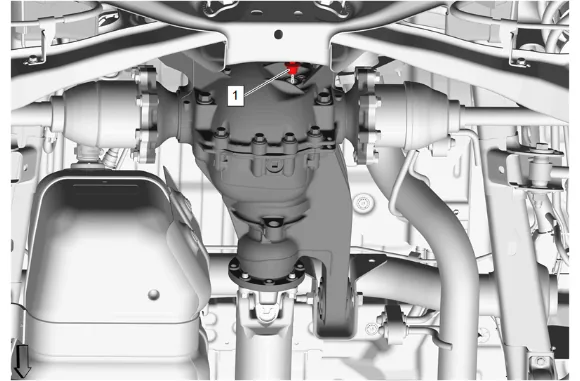
- Rear Axle Housing Fill Plug (1) » Remove
- Fill the rear differential carrier with the appropriate amount and type of axle lubricant: Adhesives, Fluids, Lubricants, and Sealers Approximate Fluid Capacities
- The gear lubricant level should be 0 - 5 mm (0.0 - 0.20 in) below the bottom of the fill plug opening.
- Rear Axle Housing Fill Plug (1) » Install and tighten — Fastener Specifications
- Remove the support and lower the vehicle.
- Install the spare tire.