Fuel Feed Pipe Replacement - Engine (L84)
Engine Controls and Fuel - 5.3L L84 or 6.2L L87 | Repair Instructions | Document ID: 5694432 Single Use Fasteners and Components Intake Manifold Gasket [8x]
- Relieve the fuel system pressure. Fuel Pressure Relief
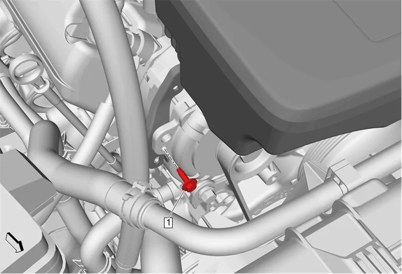
- Air Cleaner Outlet Duct Bracket Bolt (1) » Remove
- Remove engine wiring harness from air cleaner outlet duct bracket.
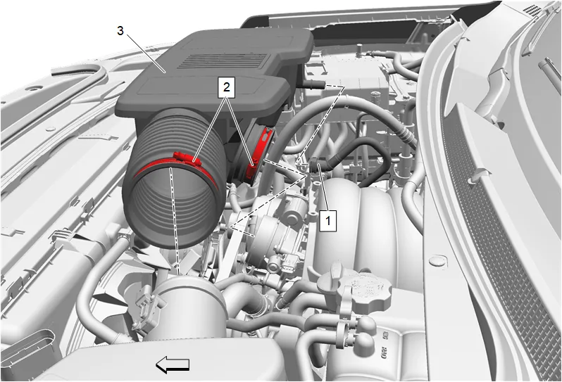
- Positive Crankcase Ventilation Fresh Air Tube (1) » Disconnect — Plastic Collar Quick Connect Fitting Service
- Air Cleaner Outlet Duct Clamp (2) » Loosen [2x]
- Air Cleaner Outlet Duct (3) » Remove
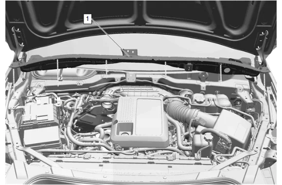
- Plenum Front Panel Outer Reinforcement (1) » Remove — Plenum Front Panel Outer Reinforcement Removal and Installation
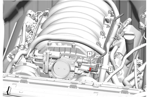
- Evaporative Emission Canister Purge Tube Connector (1) @ Evaporative Emission Canister Purge Solenoid Valve » Disengage — Plastic Collar Quick Connect Fitting Service
- Evaporative Emission Canister Purge Tube (2) @ Evaporative Emission Canister Purge Solenoid Valve » Remove and position aside
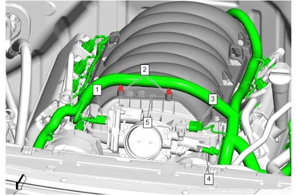
- Engine Wiring Harness Connector (1) @ Throttle Body » Disconnect
- Engine Wiring Harness Retainer (2) @ Intake Manifold Cover » Remove [2x]
- Engine Wiring Harness Connector (3) @ Manifold Absolute Pressure Sensor » Disconnect
- Engine Wiring Harness Connector (4) @ Evaporative Emission Canister Purge Solenoid Valve » Disconnect
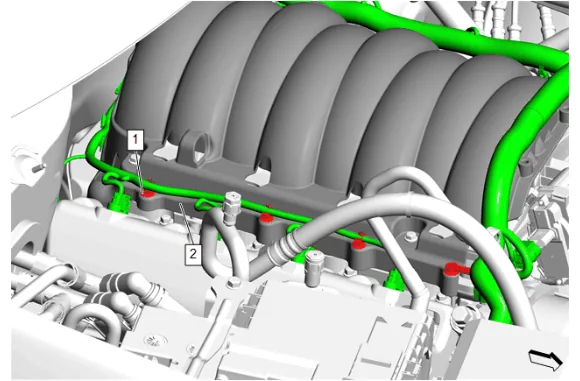
- Engine Wiring Harness Retainer (1) @ Intake Manifold Cover (2) » Remove [4x]
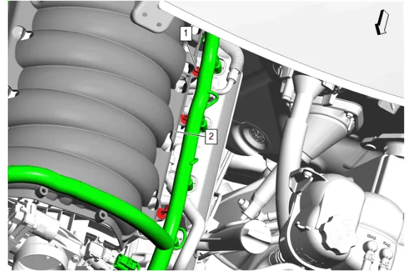
- Engine Wiring Harness Retainer (1) @ Intake Manifold Cover (2) » Remove [3x]
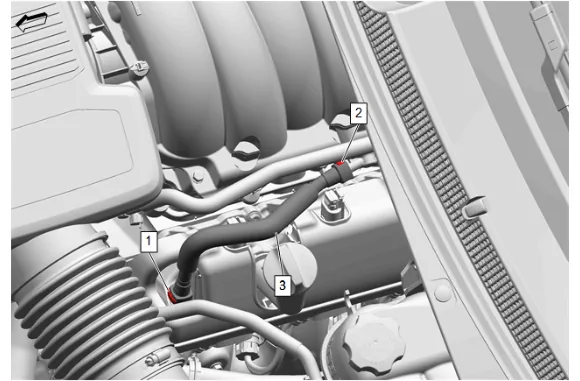
- Positive Crankcase Ventilation Tube Connector (2) @ Intake Manifold » Disconnect and reposition — Plastic Collar Quick Connect Fitting Service
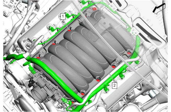
- Loosen the 10 intake manifold bolts (1) until the bolts are no longer threaded into the cylinder heads.
- Move the intake manifold and intake manifold cover (2) forward enough to gain access to the rear engine wiring harness retainers.
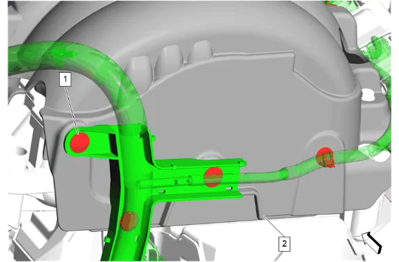
- Engine Wiring Harness Retainer (1) @ Intake Manifold Cover (2) » Remove [4x]
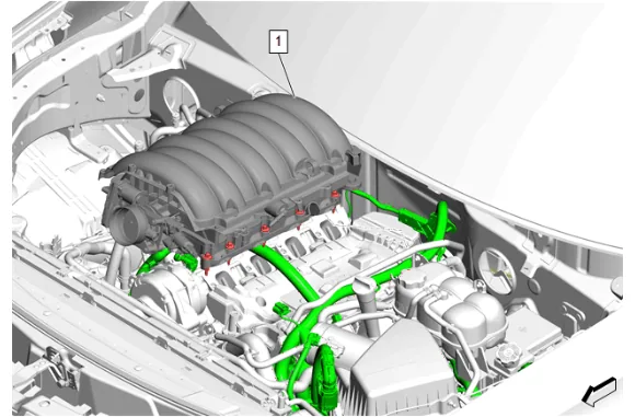
- Remove the intake manifold and intake manifold cover (1) as an assembly.
- Cover the cylinder head passages in order to prevent dirt or debris from entering the passages.
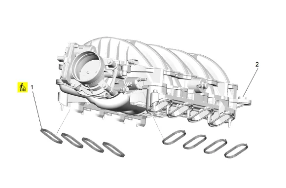
- Intake Manifold Gasket (1) » Remove and DISCARD [8x]
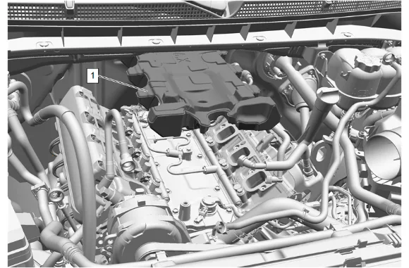
Danger: The noise cancelling foam component MUST be replaced if it has been exposed to engine fluids. Failure to replace the noise cancelling foam component that has been exposed to engine fluids may result in an engine fire resulting in catastrophic engine damage, and possible injury or death. 23. Fuel Pump Insulator (1) » Remove
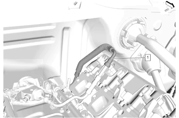
- Fuel Feed Pipe (1) » Disconnect — Metal Collar Quick Connect Fitting Service
- Fuel Feed Pipe (1) » Reposition
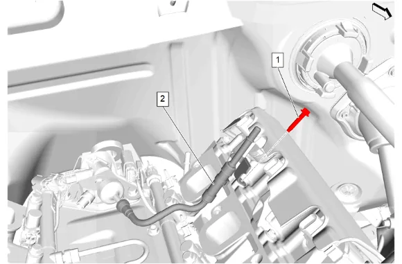
- Fuel Feed Pipe Bolt (1) » Remove
- Fuel Feed Pipe (2) » Disconnect — Metal Collar Quick Connect Fitting Service
- Fuel Feed Pipe (2) » Remove Cleaning and Inspection Procedure - Conditional
-
Clean all sealing surfaces.
-
Dry the intake manifold with compressed air.
-
Inspect the intake manifold cylinder head deck for warpage.
-
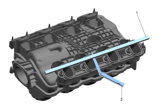
Place a straight edge (1) across the intake manifold cylinder head deck surface.
-
Inspect the intake manifold for the following conditions: 5.1. Inspect for loose threaded inserts or studs. 5.2. Inspect for damaged or broken vacuum fitting. 5.3. Inspect the intake manifold assembly for cracks or other damage. 5.4. Inspect for damaged intake manifold gasket sealing surfaces.
-
Position the straight edge (1) across a minimum of two runner port openings and check for warpage using a feeler gage. Engine Mechanical Specifications
-
Inspect the ventilation system passages for restrictions. Installation Procedure
-
Fuel Feed Pipe (2) » Install
-
Fuel Feed Pipe (2) » Connect — Metal Collar Quick Connect Fitting Service
-
Fuel Feed Pipe Bolt (1) » Install and tighten — Fastener Specifications
-
Fuel Feed Pipe (1) » Install
-
Fuel Feed Pipe (1) » Connect — Metal Collar Quick Connect Fitting Service
Danger: The noise cancelling foam component MUST be replaced if it has been exposed to engine fluids. Failure to replace the noise cancelling foam component that has been exposed to engine fluids may result in an engine fire resulting in catastrophic engine damage, and possible injury or death. 6. Fuel Pump Insulator (1) » Install
-
Intake Manifold Gasket (1) » Install NEW [8x]
-
Remove the covers from the cylinder head passages.
-
Clean all sealing surfaces.
-
If NEW threaded components are being installed, loosen the adhesive using a metal pick or similar tool before proceeding. If threaded components are reused, prepare the threaded components using the following steps: 10.1. Remove any loose cured adhesive from the external threads of the components using a lint free cloth. 10.2. Thread the cleaned components into the internal mating threads and remove to loosen trapped cured adhesive. 10.3. Apply thread locking adhesive to the external threads of the components. Adhesives, Fluids, Lubricants, and Sealers 10.4. Ensure there are no gaps in the thread locking adhesive once applied to the component.
-
Position the intake manifold and Intake manifold cover (1) to install harness retainers.
-
Engine Wiring Harness Retainer (1) @ Intake Manifold Cover (2) » Install [4x]
-
Move the intake manifold and intake manifold cover (2) into place.
-
Intake Manifold Bolt (1) » Hand tighten [10x]
-
Intake Manifold Bolt (1) » Tighten in sequence [10x] — Fastener Specifications
-
Positive Crankcase Ventilation Tube Connector (2) @ Intake Manifold » Install — Plastic Collar Quick Connect Fitting Service
-
Engine Wiring Harness Retainer (1) @ Intake Manifold Cover (2) » Install [3x]
-
Engine Wiring Harness Retainer (1) @ Intake Manifold Cover (2) » Install [4x]
-
Engine Wiring Harness Connector (4) @ Evaporative Emission Canister Purge Solenoid Valve » Connect
-
Engine Wiring Harness Connector (3) @ Manifold Absolute Pressure Sensor » Connect
-
Engine Wiring Harness Retainer (2) @ Intake Manifold Cover » Install [2x]
-
Engine Wiring Harness Connector (1) @ Throttle Body » Connect
-
Evaporative Emission Canister Purge Tube (2) @ Evaporative Emission Canister Purge Solenoid Valve » Install
-
Evaporative Emission Canister Purge Tube Connector (1) @ Evaporative Emission Canister Purge Solenoid Valve » Engage — Plastic Collar Quick Connect Fitting Service
-
Plenum Front Panel Outer Reinforcement (1) » Install — Plenum Front Panel Outer Reinforcement Removal and Installation
-
Air Cleaner Outlet Duct (3) » Install
-
Air Cleaner Outlet Duct Clamp (2) » Tighten [2x] — Fastener Specifications
-
Positive Crankcase Ventilation Fresh Air Tube (1) » Connect — Plastic Collar Quick Connect Fitting Service
-
Air Cleaner Outlet Duct Bracket Bolt (1) » Install and tighten — Fastener Specifications
-
Install engine wiring harness to air cleaner outlet duct bracket.
-
Pressurize the fuel system and inspect for leaks.
-
Inspect for fuel leaks.