Body Mount Upper Location Number 4 Cushion Replacement
Body Mount Upper Location Number 4 Cushion Replacement Single Use Fasteners and Components Fuel Tank Filler Pipe Housing Removal Procedure
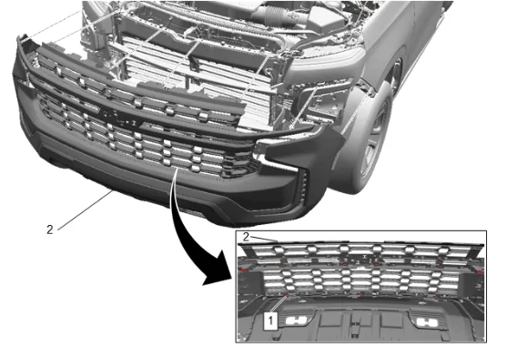
- Front Bumper Fascia (1) » Remove — Front Bumper Fascia Removal and Installation
- Remove the front tire and wheel assembly. Tire and Wheel Removal and Installation
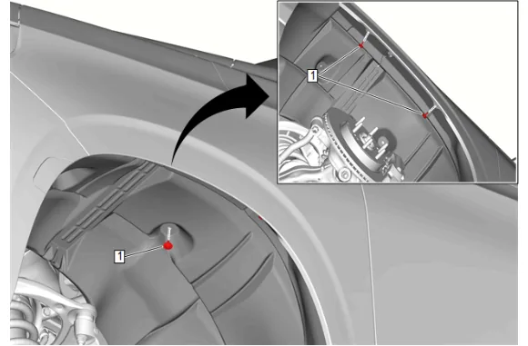
- Front Wheelhouse Liner Bolt (1) » Remove [3x]
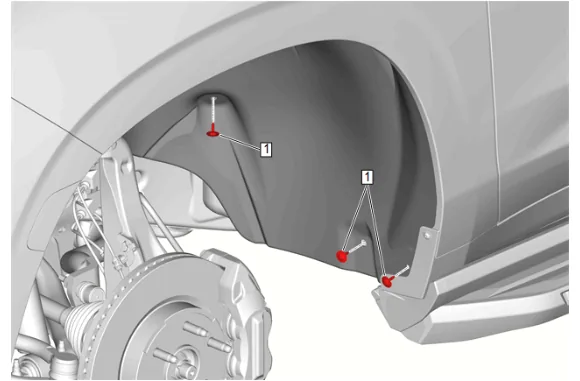
- Front Wheelhouse Liner Bolt (1) » Remove [3x]
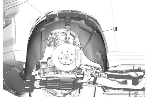
- Front Wheelhouse Liner (1) » Remove
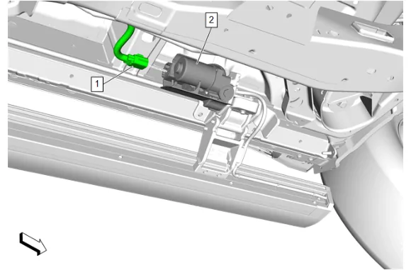
- {with B3L} Extend the assist steps in the vehicle personal optimization chapter in the owners manual.
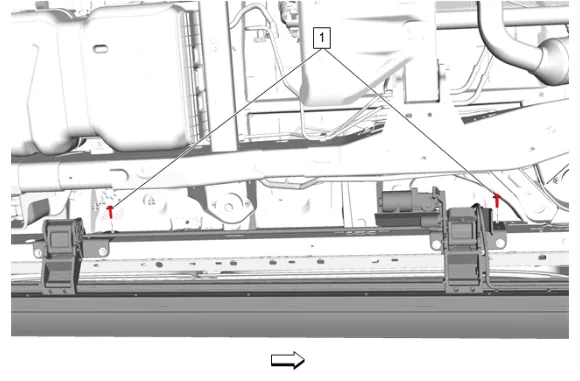
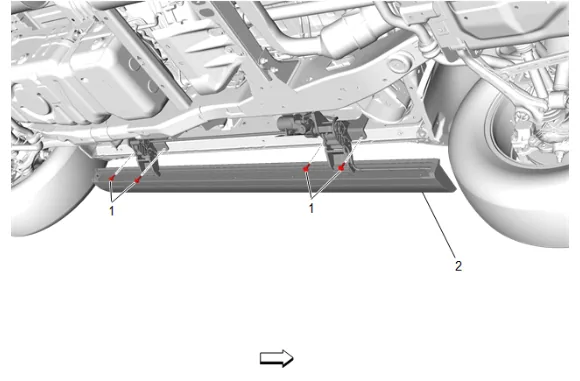
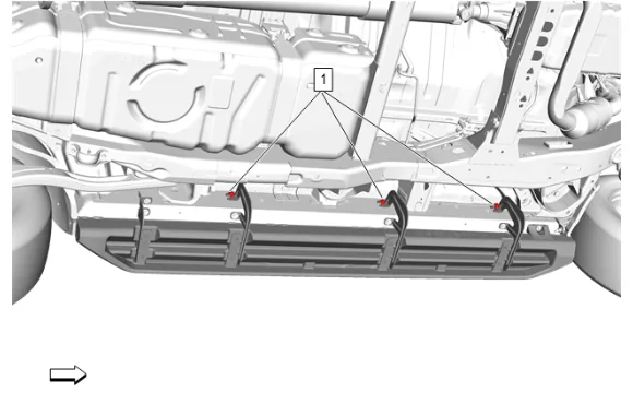
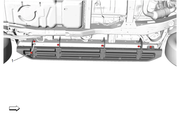
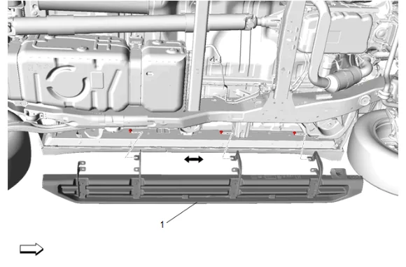
- {with BVE} Assist Step Bolt (1) @ Rocker Panel » Loosen [3x]
- Secure the steering wheel so it will not turn when the upper intermediate steering shaft and steering column are disconnected.
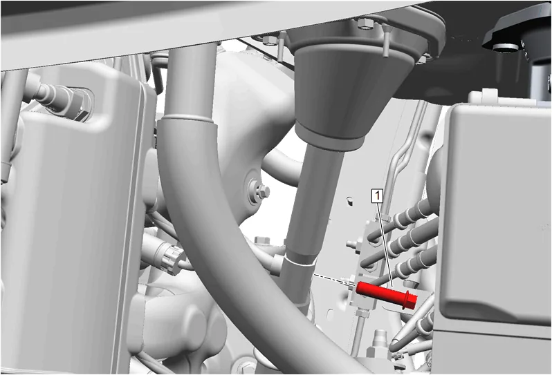
- Mid Intermediate Steering Shaft Bolt (1) » Remove
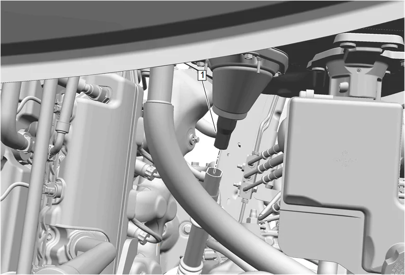
- Upper Intermediate Steering Shaft (1) @ Intermediate Steering Shaft » Separate
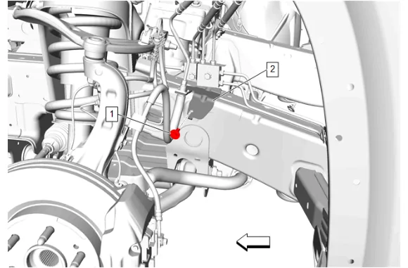
- Front Brake Hose Bracket Bolt (1) » Remove
- Front Brake Hose Bracket (2) » Reposition away
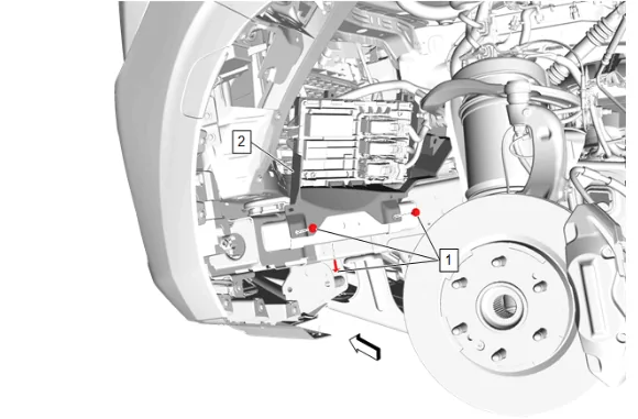
- Engine Control Module Bracket Bolt » Remove [3x]
- Engine Control Module Bracket (2) » Reposition away
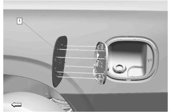
- Position the fuel tank filler door (1) to the fill open position.
- Using the appropriate tool, release the filler door retainers and remove the fuel tank filler door (1).
- {with LM2} Remove the emission reduction fluid tank filler pipe cap.
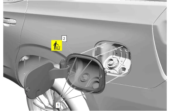
- Using a flat-bladed tool that fits into the 4 depressions (1) , break through the 4 depressions with light pressure and then pry the clips free to release the fuel tank filler pipe housing from the body side outer panel.
- Fuel Tank Filler Pipe Housing (2) » Remove and DISCARD
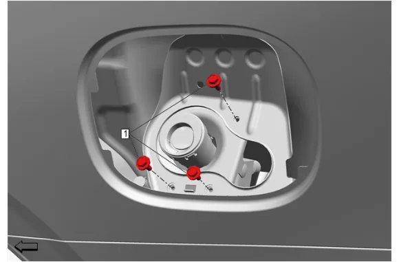
- Fuel Tank Filler Pipe Ground Bolt (1) » Remove [3x]
- Install the tire and wheel assembly. Tire and Wheel Removal and Installation
- Lower the vehicle.
- Support the radiator with mechanics wire or something similar.
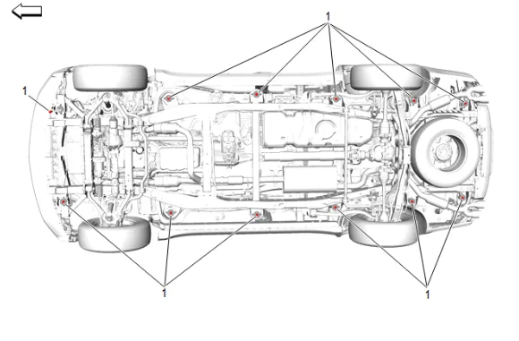
- Remove the 12 body mount bolts and washers (1).
- Reposition the vehicle hoist onto the body pinch welds.
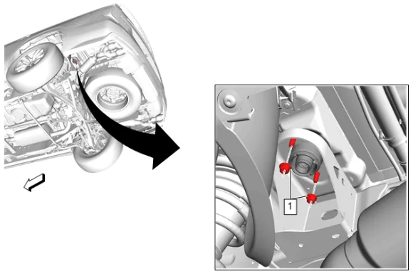
Body Mount Nut (1) » Remove [2x]
- Slowly raise the cab on the hoist approximately 76.2 mm (3 in) while observing the clearance needed to remove the body mount upper location number 4 cushion.
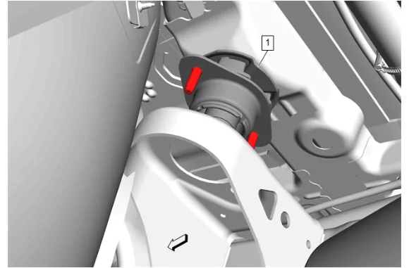
-
Body Mount Upper Location Number 4 Cushion (1) » Remove Installation Procedure
-
Body Mount Upper Location Number 4 Cushion (1) » Install
-
Lower the vehicle.
-
Reposition the vehicle hoist onto the frame rail.
-
Raise and support the vehicle. Lifting and Jacking the Vehicle
-
Remove the front tire and wheel assembly. Tire and Wheel Removal and Installation
-
Body Mount Nut (1) » Install and tighten [2x] — Fastener Specifications
-
Perform the following procedure before installing the body mount bolts (1) : 7.1. Remove any loose cured adhesive from the external threads of the components using a lint free cloth. 7.2. Thread the cleaned components into the internal mating threads and remove to loosen trapped cured adhesive. 7.3. Apply thread locking adhesive to the external threads of the components. Adhesives, Fluids, Lubricants, and Sealers 7.4. Ensure there are no gaps in the thread locking adhesive once applied to the component.
-
Install and hand tighten the 12 body mount washers and bolts (1).
-
Body Mount Bolt (1) » Tighten [12x] — Fastener Specifications
-
Fuel Tank Filler Pipe Ground Bolt (1) » Install and tighten [3x] — Fastener Specifications
-
Fuel Tank Filler Pipe Housing (2) » Install NEW
-
Press the fuel tank filler pipe housing depressions (1) to the body side outer panel until fully seated.
-
Ensure the fuel tank filler pipe housing seal is full seated to the filler pipe.
-
{with LM2} Install the emission reduction fluid tank filler pipe cap.
-
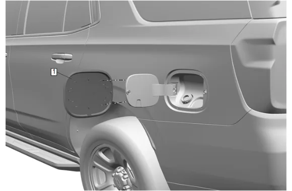
Fuel Tank Filler Door (1) » Install
-
Engine Control Module Bracket (2) » Install
-
Engine Control Module Bracket Bolt » Install and tighten [3x] — Fastener Specifications
-
Front Brake Hose Bracket (2) » Install
-
Front Brake Hose Bracket Bolt (1) » Install and tighten — Fastener Specifications
-
Upper Intermediate Steering Shaft (1) @ Intermediate Steering Shaft » Install
-
If a NEW threaded component is being installed, loosen the adhesive using a metal pick or similar tool before proceeding. If threaded component is reused, prepare the threaded component using the following steps: 21.1. Remove any loose cured adhesive from the external threads of the component using a lint free cloth. 21.2. Thread the cleaned component into the internal mating threads and remove to loosen trapped cured adhesive. 21.3. Apply thread locking adhesive to the external threads of the component. Adhesives, Fluids, Lubricants, and Sealers 21.4. Ensure there are no gaps in the thread locking adhesive once applied to the component.
-
Mid Intermediate Steering Shaft Bolt (1) » Install and tighten — Fastener Specifications
-
Front Wheelhouse Liner (1) » Install
-
Front Wheelhouse Liner Bolt (1) » Install and tighten [3x] — Fastener Specifications
-
Front Wheelhouse Liner Bolt (1) » Install and tighten [3x] — Fastener Specifications
-
{with BVE} Install the assist step (1) under the loosened bolts.
26.1. Assist Step Bolt (1) @ Rocker Panel » Install and tighten [6x] — Fastener Specifications
26.2. Assist Step Bolt (1) @ Rocker Panel » Tighten [3x] — Fastener Specifications
- {with B3L} Assist Step (2) » Install 27.1. Assist Step Bolt (1) Install and tighten [4x] — Fastener Specifications
27.2. Assist Step Bolt (1) » Install and tighten [2x] — Fastener Specifications
27.3. Electrical Connector (1) @ Assist Step Motor (2) » Connect
- Front Bumper Fascia (1) » Install — Front Bumper Fascia Removal and Installation
- Install the front tire and wheel assembly. Tire and Wheel Removal and Installation