Steering Column Replacement (N33, N37)
- Install an appropriate device to prevent the steering column from rotating.
- Disable the SIR system. SIR Disabling and Enabling
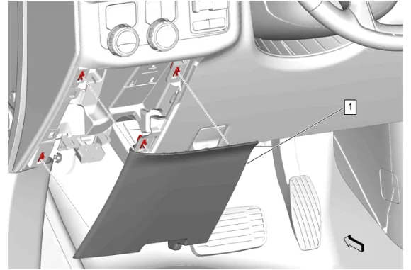
- Instrument Panel Lower Trim Panel Outer Filler (1) » Remove
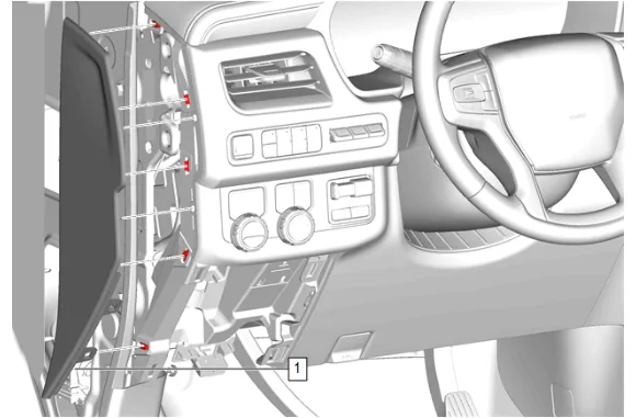
- Using a flat-bladed plastic trim tool, release the retaining clips.
- Instrument Panel Fuse Block Access Hole Cover (1) » Remove
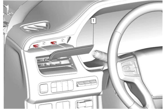
- Using a flat-bladed plastic trim tool, release the retaining clips.
- Instrument Panel Trim Plate Applique (1) » Remove
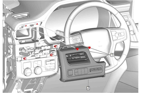
- Instrument Panel Trim Pad Bolt (1) » Remove [2x]
- Disconnect the electrical connectors.
- Instrument Panel Trim Pad (2) » Remove
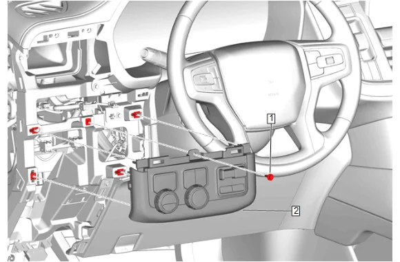
- Instrument Panel Switch Trim Plate Bolt (1) » Remove
- Disconnect the electrical connectors.
- Instrument Panel Switch Trim Plate (2) » Remove
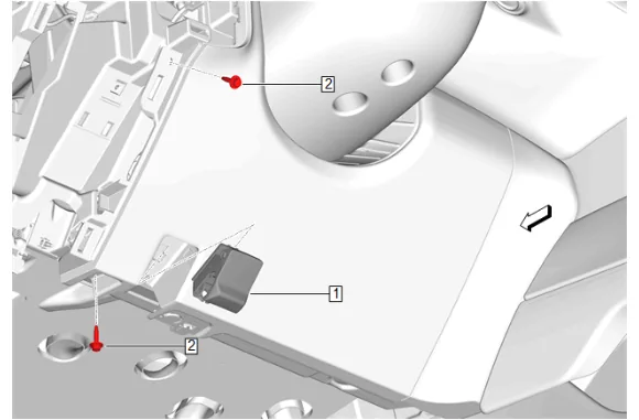
- Hood Primary Latch Release Cable Handle (1) » Release
- Instrument Panel Knee Bolster Bolt (2) » Remove [2x]
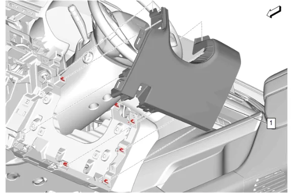
- Instrument Panel Knee Bolster (1) » Remove
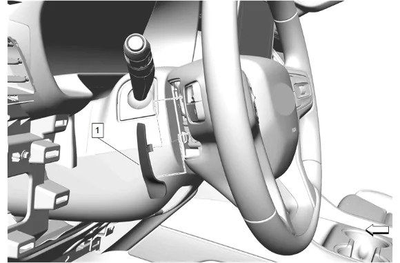
- Use a flat bladed trim tool to depress the steering wheel airbag access hole cover detents to remove the 2 steering wheel airbag access hole covers (1).
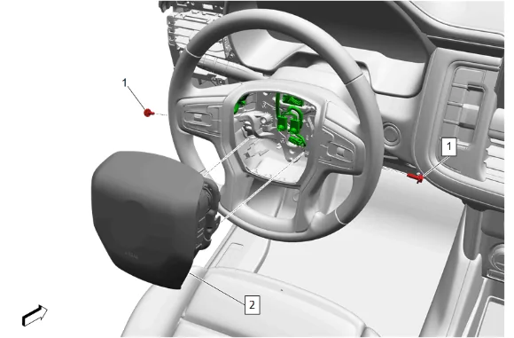
- Steering Wheel Airbag Bolt (1) » Remove [2x]
- Release the connector position assurance (CPA) retainer.
- Disconnect the electrical connectors.
- Steering Wheel Airbag (2) » Remove
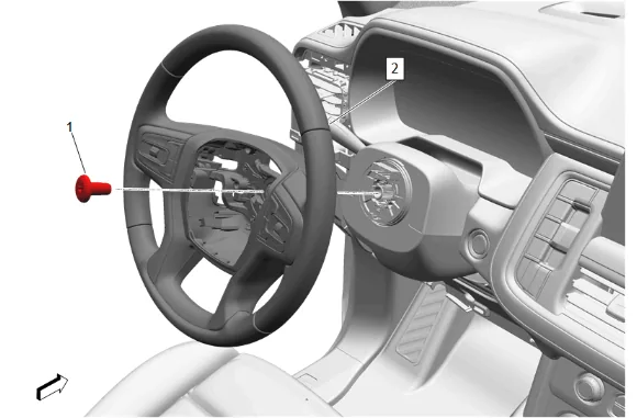
- Loosen the steering wheel bolt (1) so that 2 - 3 threads are engaged.
- Wiggle the steering wheel until the wheel disengages completely.
- Steering Wheel Bolt (1) » Remove
- Steering Wheel (2) » Remove
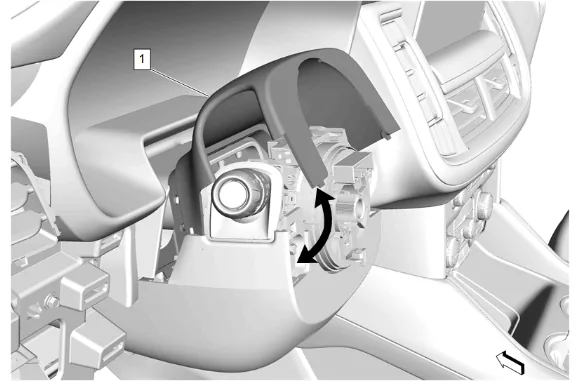
- Using a small plastic trim tool, separate the instrument panel steering column upper trim cover (1) from the instrument panel steering column lower trim cover.
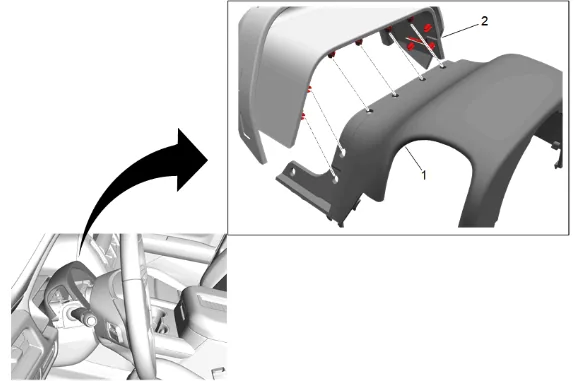
- Using a small plastic trim tool, separate the instrument panel steering column upper trim cover (1) from the instrument panel steering column opening closeout (2).
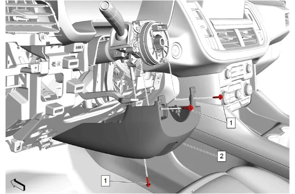
- Instrument Panel Steering Column Lower Trim Cover Bolt (1) » Remove [3x]
- Instrument Panel Steering Column Lower Trim Cover (2) » Remove
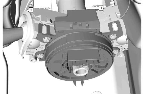
- Disengage the steering wheel airbag coil upper retaining tabs (1).
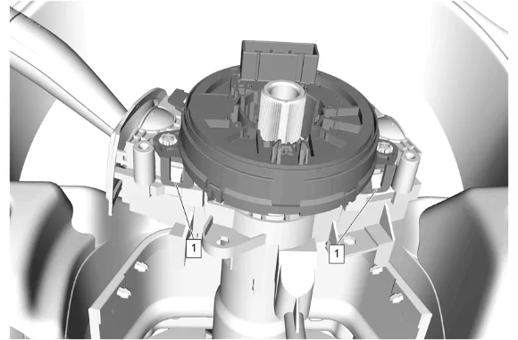
- Disengage the steering wheel airbag coil lower retaining tabs (1).
- Disconnect the electrical connector.
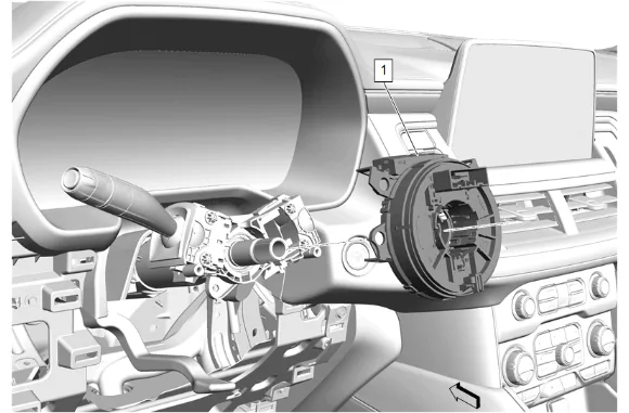
- Steering Wheel Airbag Coil (1) » Remove
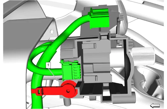
- Remove the wiring harness clip (1) on the left side of the turn signal bracket.
- Reposition the wiring harness.
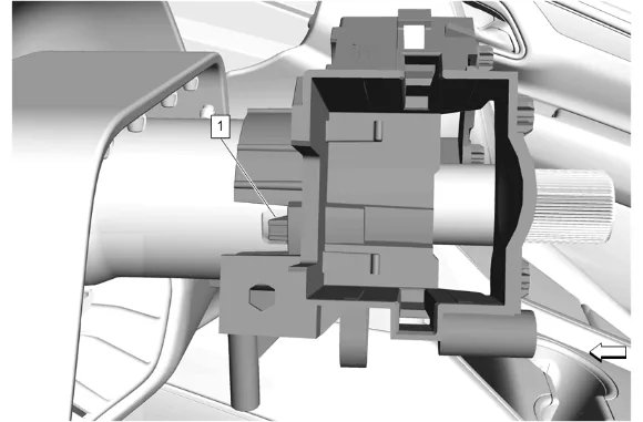
- Release the locking tab (1) on the left side of the turn signal switch bracket.
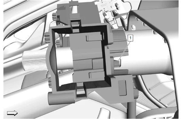
- Release the locking tab (1) on the right side of the turn signal switch bracket.
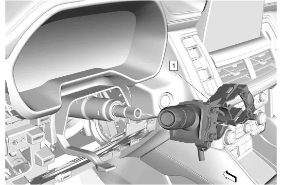
- Remove the turn signal switch and turn signal switch bracket (1) as an assembly.
- Disconnect the electrical connector.
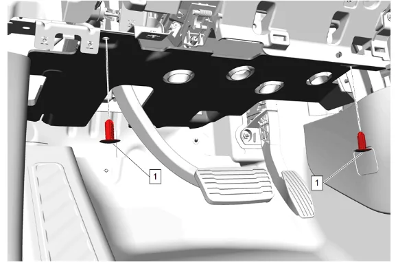
- Instrument Panel Lower Insulator Retainer (1) » Remove [2x]
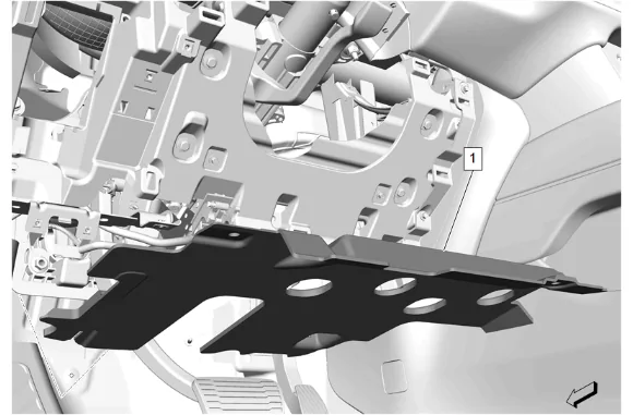
- Instrument Panel Lower Trim Panel Insulator (1) » Remove
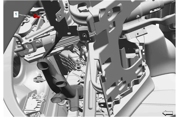
- Floor Front Air Outlet Duct Bolt (1) » Remove
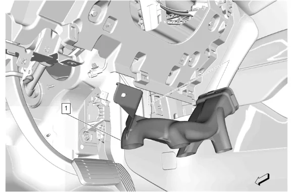
- Floor Front Air Outlet Duct - Left Side (1) » Remove
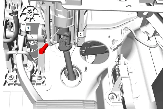
- Upper Intermediate Steering Shaft Bolt (1) » Remove
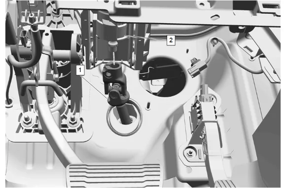
- Upper Intermediate Steering Shaft (1) @ Steering Column (2) » Separate
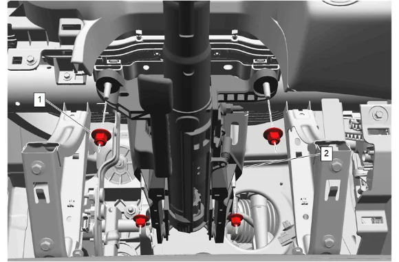
- Steering Column Nut (1) » Remove [4x]
- Disconnect the electrical connectors attached to the steering column (2).
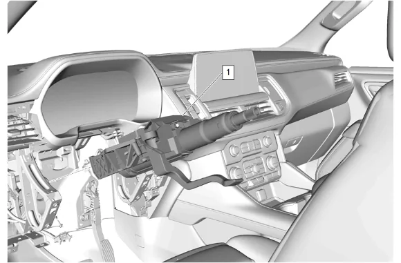
- Steering Column (1) » Remove
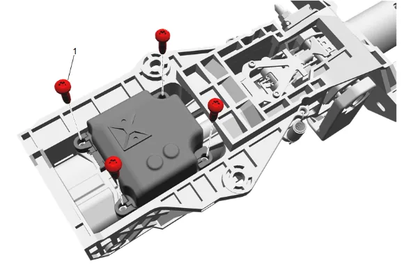
- Steering Column Lock Control Module Bolt (1) » Remove [4x]
-
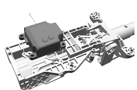
Column Lock Module (1) » Remove Installation Procedure
-
Column Lock Module (1) » Install
-
Steering Column Lock Control Module Bolt (1) » Install and tighten [4x] — Fastener Specifications
-
Steering Column (1) » Install
-
Connect the electrical connectors attached to the steering column (1).
-
Steering Column Nut (1) » Install and tighten [4x] — Fastener Specifications
-
Upper Intermediate Steering Shaft (1) » Install
-
Upper Intermediate Steering Shaft Bolt (1) » Install and tighten — Fastener Specifications
-
Floor Front Air Outlet Duct - Left Side (1) » Install
-
Floor Front Air Outlet Duct Bolt (1) » Install and tighten — Fastener Specifications
-
Instrument Panel Lower Trim Panel Insulator (1) » Install
-
Instrument Panel Lower Insulator Retainer (1) » Install [2x]
-
Connect the electrical connector.
-
Install turn signal switch and turn signal switch bracket (1) as an assembly.
-
Ensure the locking tab on the right side of the turn signal switch bracket is fully seated.
-
Ensure the locking tab on the left side of the turn signal switch bracket is fully seated.
-
Wiring Harness » Move into position
-
Install the wiring harness clip (1) on the left side of the turn signal bracket.
-
Ensure the steering wheel airbag coil is CENTERED during installation. Steering Wheel Airbag Coil Centering
-
Steering Wheel Airbag Coil (1) » Install
-
Connect the electrical connectors.
-
Instrument Panel Steering Column Lower Trim Cover (2) » Install
-
Instrument Panel Steering Column Lower Trim Cover Bolt (1) » Install and tighten [3x] — Fastener Specifications
-
Clip the instrument panel steering column opening closeout (2) to the instrument panel steering column upper trim cover (1).
-
Secure the instrument panel steering column upper trim cover (1) to the instrument panel steering column lower trim cover.
-
Steering Wheel (2) » Install
-
If a NEW threaded component is being installed, loosen the adhesive using a metal pick or similar tool before proceeding. If threaded component is reused, prepare the threaded component using the following steps: 26.1. Remove any loose cured adhesive from the external threads of the component using a lint free cloth. 26.2. Thread the cleaned component into the internal mating threads and remove to loosen trapped cured adhesive. 26.3. Remove loose debris from internal and external threads using compressed air. 26.4. Apply liquid thread locking adhesive in a strip along half of the length of the external threads, starting at the tip, just prior to installation. Adhesives, Fluids, Lubricants, and Sealers
-
Steering Wheel Bolt (1) » Install and tighten — Fastener Specifications
-
Connect the electrical connectors.
-
Install any connector position assurance (CPA) devices or secondary locks.
-
Steering Wheel Airbag (2) » Install
-
Steering Wheel Airbag Bolt (1) » Install and tighten — Fastener Specifications
-
Install the 2 steering wheel airbag access hole covers (1).
-
Instrument Panel Knee Bolster (1) » Install
-
Instrument Panel Knee Bolster Bolt (2) » Install and tighten [2x] — Fastener Specifications
-
Hood Primary Latch Release Cable Handle (1) » Install
-
Connect the electrical connectors.
-
Instrument Panel Switch Trim Plate (2) » Install
-
Instrument Panel Switch Trim Plate Bolt (1) » Install and tighten — Fastener Specifications
-
Connect the electrical connectors.
-
Instrument Panel Trim Pad (2) » Install
-
Instrument Panel Trim Pad Bolt (1) » Install and tighten [2x] — Fastener Specifications
-
Instrument Panel Trim Plate Applique (1) » Install
-
Instrument Panel Fuse Block Access Hole Cover (1) » Install
-
Instrument Panel Lower Trim Panel Outer Filler (1) » Install
-
Enable the SIR System. SIR Disabling and Enabling
-
Remove the device used to prevent steering column rotation.