Fuel Feed Pipe Replacement
Single Use Fasteners and Components Tie Strap
- Turn OFF the engine for 30 seconds before proceeding to purge the fuel pressure from the complete fuel system.
- Front Wheelhouse Liner - Left Side » Remove — Front Wheelhouse Liner Replacement
- Disconnect all wiring harness retainers from the fuel feed and fuel return pipe.
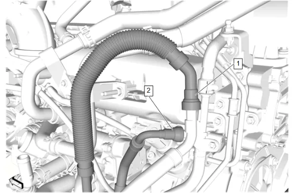
- Fuel Feed Pipe (1) » Disconnect — Metal Collar Quick Connect Fitting Service
- Fuel Return Pipe (2) » Disconnect — Metal Collar Quick Connect Fitting Service
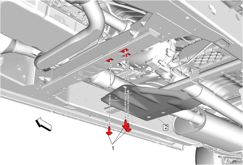
- { If equipped } Transfer Case Skid Shield Bolt (1) » Remove [3x]
- { If equipped } Transfer Case Skid Shield (2) » Remove
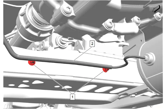
- {with F47} Unclip the 2 air line retainers (1) and reposition the air line (2).
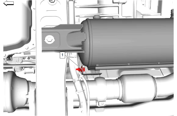
- {with F47} Remove the chassis wire harness clip (1) from the automatic level control air supply reservoir.
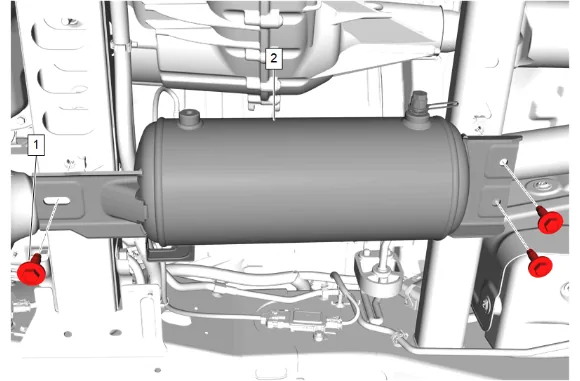
- {with F47} Remove the 3 automatic level control air compressor bolts (1).
- {with F47} Reposition and support the automatic level control air supply reservoir (2) out of the way of the transmission support crossmember.
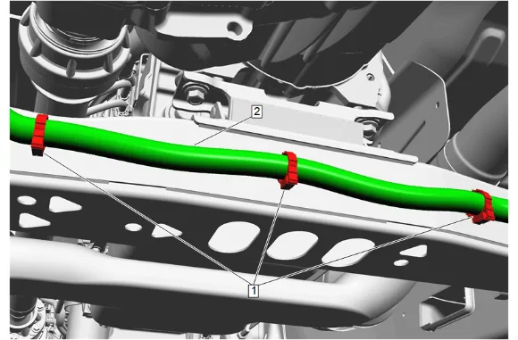
- { If equipped } Remove the 3 wiring harness retainers (1) from the transmission support crossmember, and reposition the wiring harness (2) as necessary.
- Support the transmission with a suitable jack.
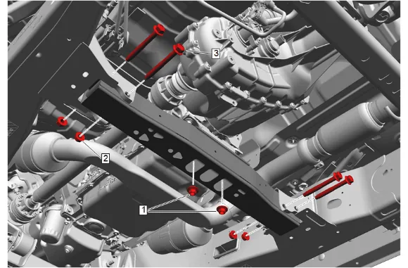
- Transmission Mount Nut (1) » Remove [2X]
- Transmission Support Crossmember Nut (2) » Remove [4x]
- Transmission Support Crossmember Bolt (3) » Remove [4x]
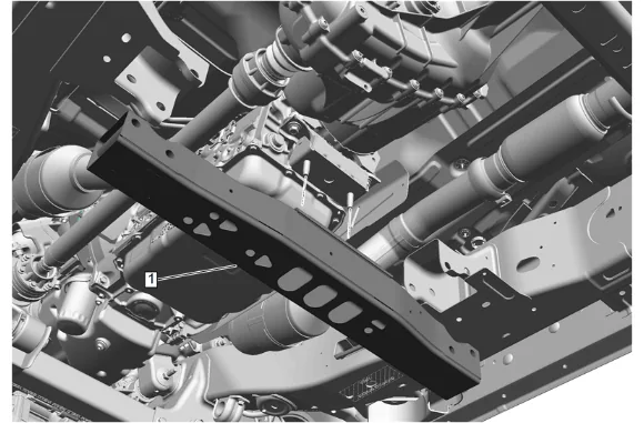
- Transmission Support Crossmember (1) » Remove
- Lower the transmission to gain access to the top and sides of the transmission.
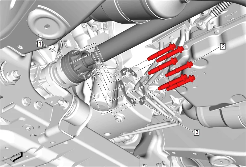
- Mark a reference point between the front axle propeller shaft (1) and the front differential drive pinion gear yoke.
- Front Axle Propeller Shaft Bolt (2) » Remove [6x]
- Front Axle Propeller Shaft Washer (3) » Remove [3x]
- Front Axle Propeller Shaft (1) » Reposition away
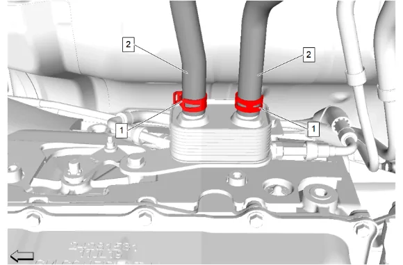
- Hose Clamp (1) » Disengage [2x] — Hose Clamp Replacement Guidelines - Spring Type
- Fuel Cooler Coolant Cooler Inlet Hose (2) » Remove and position aside [2x]
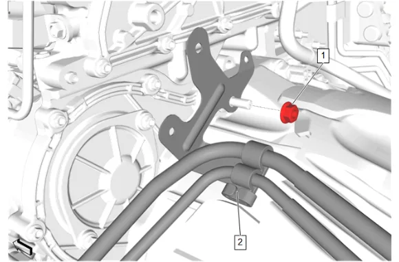
- Fuel Feed and Return Front Hose Bracket Nut (1) » Remove
- Fuel Feed and Return Pipe (2) » Remove
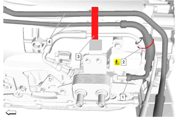
- Fuel Return Pipe (1) » Disconnect — Metal Collar Quick Connect Fitting Service
- Tie Strap (2) » Remove and DISCARD
- Fuel Feed and Return Pipe (4) @ Retainer (3) » Disengage
- { If equipped } Remove the transfer case vent hose retainers.
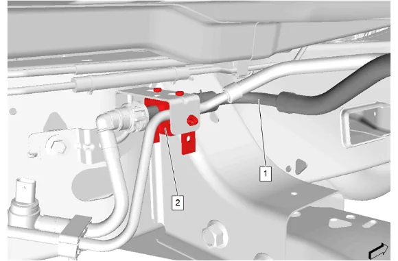
- Fuel Feed and Return Pipe (1) » Disconnect — Plastic Collar Quick Connect Fitting Service
- Fuel Feed and Return Pipe (1) @ Retainer (2) » Disengage
- Fuel Feed and Return Pipe (1) » Remove
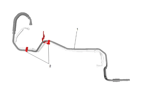
-
Fuel Feed Pipe (1) @ Retainer (2) » Disengage [2x]
-
Fuel Feed Pipe (1) » Remove Installation Procedure
-
Fuel Feed Pipe (1) » Install
-
Fuel Feed Pipe (1) @ Retainer (2) » Engage [2x]
-
Fuel Feed and Return Pipe (1) » Install
-
Fuel Feed and Return Pipe (1) @ Retainer (2) » Engage
-
Fuel Feed and Return Pipe (1) » Connect — Plastic Collar Quick Connect Fitting Service
-
Fuel Feed and Return Pipe (4) @ Retainer (3) » Engage
-
Tie Strap (2) » Install NEW
-
Fuel Return Pipe (1) » Connect — Metal Collar Quick Connect Fitting Service
-
{ If equipped } Install the transfer case vent hose retainers.
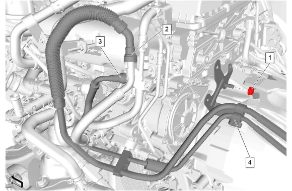
- Fuel Feed and Return Pipe (4) » Install
- Fuel Return Pipe (3) » Connect — Metal Collar Quick Connect Fitting Service
- Fuel Feed Pipe (2) » Connect — Metal Collar Quick Connect Fitting Service
-
Fuel Feed and Return Front Hose Bracket Nut (1) » Install and tighten — Fastener Specifications
-
Connect all wiring harness retainers to the fuel feed and fuel return pipe.
-
Raise transmission to installed position.
-
If NEW threaded components are being installed, loosen the adhesive using a metal pick or similar tool before proceeding. If threaded components are reused, prepare the threaded components using the following steps: 16.1. Remove any loose cured adhesive from the external threads of the components using a lint free cloth. 16.2. Thread the cleaned components into the internal mating threads and remove to loosen trapped cured adhesive. 16.3. Apply thread locking adhesive to the external threads of the components. Adhesives, Fluids, Lubricants, and Sealers 16.4. Ensure there are no gaps in the thread locking adhesive once applied to the component.
-
Front Axle Propeller Shaft (1) » Reposition
-
Align the reference marks made between the front axle propeller shaft (1) and the front differential drive pinion gear yoke.
-
Front Axle Propeller Shaft Washer (3) » Install [3x]
-
Install the 6 front axle propeller shaft bolts (2) and tighten in a crisscross pattern. Fastener Specifications
-
Transmission Support Crossmember (1) » Install
-
Transmission Support Crossmember Bolt (3) » Install [4x]
-
Transmission Support Crossmember Nut (2) » Install and tighten [4x] — Fastener Specifications
-
Transmission Mount Nut (1) » Install and tighten [2x] — Fastener Specifications
-
Remove the transmission jack.
-
{ If equipped } Position the wiring harness (2) as necessary and install the harness retainers (1) into the transmission support crossmember.
-
{with F47} Automatic Level Control Air Supply Reservoir (2) » Install
-
{with F47} Install the 3 automatic level control air compressor bolts (1) and tighten. Fastener Specifications
-
{with F47} Install the chassis wire harness clip (1) to the automatic level control air supply reservoir.
-
I{with F47} nstall the air line (2) and clip the 2 air line retainers (1).
-
{ If equipped } Transfer Case Skid Shield (2) » Install
-
{ If equipped } Transfer Case Skid Shield Bolt (1) » Install and tighten [3x] — Fastener Specifications
-
Fuel Cooler Coolant Cooler Inlet Hose (2) » Install [2x]
-
Hose Clamp (1) » Engage [2x] — Hose Clamp Replacement Guidelines - Spring Type
-
Front Wheelhouse Liner - Left Side » Install — Front Wheelhouse Liner Replacement
-
Prime the fuel system and inspect for fuel leaks. Fuel System Priming