Park - Engine Running (Hydraulic Circuits)
When the gear selector is in the Park (P) position, the shift solenoids A, B and are commanded ON and the following changes occur in the transmission’s hydraulic and electrical systems: Fluid Pressure Directed in Preparation for a Shift Secondary Line Fluid Circuit PUMP OUT (3) fluid from the automatic transmission fluid pump supplies constant fluid pressure to various components such as the main regulator valve, anti-backflow valve, priority valve, TCC control solenoid valve and the TCC regulator control valve. Line Fluid Circuit PUMP OUT (3) fluid is directed through the anti-backflow valve into the LINE (2) fluid circuit. LINE (2) fluid supplies constant fluid pressure to various components such as the start/stop check e-pump, etrs valve, 1-2-3-4-5-6 clutch regulator valve, 1-2- 8-9-10-R clutch regulator valve, 2-3-4-5-7-9-10 clutch regulator valve, 4-5-6-7-8-9-10-R clutch regulator valve, 1-3-5-6-7-8-9 clutch regulator valve and the 1-2-3-4-6-7-8-10-R clutch regulator valve. The anti-backflow valve requires a minimum Line VFS pressure of 107 kPa. This pressure nominally corresponds to a minimum line pressure required of 269 kPa. 1-2-3-4-5-6 Reverse Clutch Regulator Valve Shift solenoid valve A is energized and applying pressure against the 1-2-3-4-5-6 reverse clutch regulator valve allowing LINE (2) fluid to enter the 123456R CLUTCH (21) fluid circuit. 123456R CLUTCH (21) fluid is directed to the 1-2-3-4-5-6 reverse clutch assembly. 123456R CLUTCH (21) fluid is also directed through orifice #6 into the 123456R CLUTCH FEEDBACK (22) fluid passage to the #1 ball check valve which seats against the FEED LIMIT – LOW (15) fluid passage. 1-2-3-4-5-6 Reverse Clutch Assembly 123456R CLUTCH (21) fluid is directed through orifice #9 into the 1-2-3-4-5-6 reverse clutch assembly. 123456R CLUTCH (21) fluid moves the piston against spring force to apply holding of the 1-2-3-4-5-6 reverse clutch plates. 1-2-8-9-10 Reverse Clutch Regulator Valve Shift solenoid valve B is energized and applying pressure against the 1-2-8-9-10 reverse clutch regulator valve allowing LINE (2) fluid to enter the 1289-10R CLUTCH (24) fluid circuit. 1289-10R CLUTCH (24) fluid is directed to the 1-2-8-9-10 reverse clutch assembly. 1289-10R CLUTCH (24) fluid is also directed through orifice #11 into the 1289-10R CLUTCH FEEDBACK (25) fluid passage to the #2 ball check valve which seats against the FEED LIMIT – LOW (15) fluid passage. Fluid is also directed through orifice #69 to the #7 ball check valve. 1-2-8-9-10 Reverse Clutch Assembly 1289-10R CLUTCH (24) fluid is directed through orifice #14 into the 1-2-8-9-10 reverse clutch assembly. 1289-10R CLUTCH (24) fluid moves the piston against spring force to apply holding of the 1-2-8-9-10 reverse clutch plates. Park - Engine Running
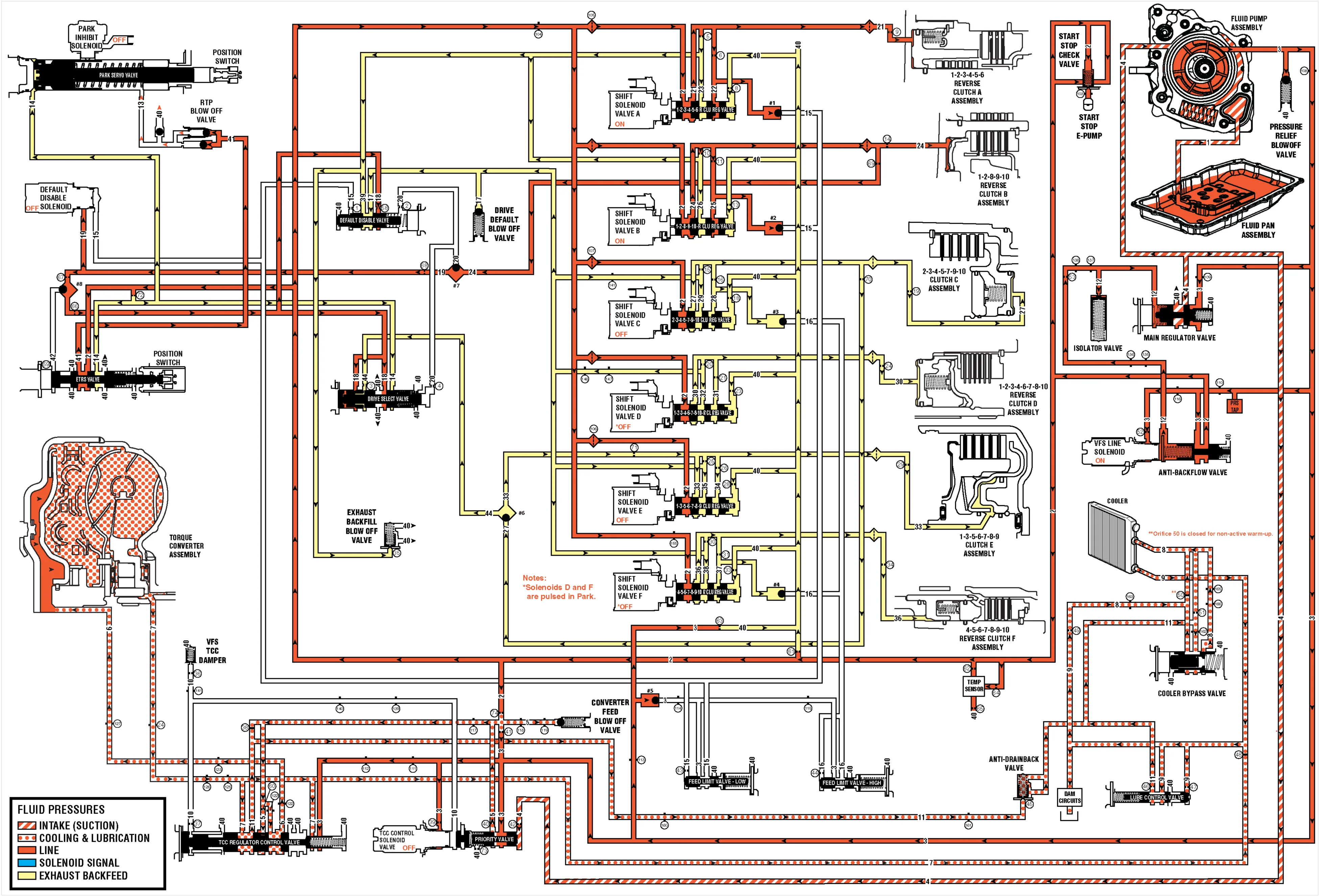
(1) Suction (2) Line (3) Pump Out (4) Decrease (5) Converter Feed (6) TCC Release (7) TCC Apply (8) Cooler Feed (9) Lube (10) VFS-TCC (11) Converter Return (12) VFS Line (13) Park On (14) Park Off (15) Feed Limit – Low (16) Feed Limit – High (17) Drive Default (18) Drive Latch (19) ON/OFF Signal (20) On/Off 1289-10 Reverse Clutch (21) 123456 Reverse Clutch (22) 123456 Reverse Clutch Feedback (23) 123456 Reverse Clutch Exhaust (24) 1289-10 Reverse Clutch (25) 1289-10 Reverse Clutch Feedback (26) 1289-10 Reverse Clutch Exhaust (27) 234579-10 Clutch (28) 234579-10 Clutch Feedback (29) 234579-10 Clutch Exhaust (30) 1234678-10 Reverse Clutch (31) 1234678-10 Reverse Clutch Feedback (32) 1234678-10 Reverse Clutch Exhaust (33) 1356789 Clutch (34) 1356789 Clutch Feedback (35) 1356789 Clutch Exhaust (36) 456789-10 Reverse Clutch (37) 456789-10 Reverse Clutch Feedback (38) 456789-10 Reverse Clutch Exhaust (39) Exhaust Backfill (40) Exhaust (41) Return to Park (42) On/Off Drive Latch (44) 234579-10/1356789 CLUTCH