Electric Belt Drive Rack and Pinion Steering Gear Replacement (L84, L87, without RC1)
Electric Belt Drive Rack and Pinion Steering Gear Replacement (L84, L87, without RC1) Special Tools Steering Linkage CH-43631 Ball Joint Separator Equivalent regional tools: Special Tools Removal Procedure
- Disconnect the battery negative cable. Battery Negative Cable Disconnection and Connection
- Secure the steering wheel so it will not turn when the upper intermediate steering shaft and steering column are disconnected.
- Raise and support the vehicle. Lifting and Jacking the Vehicle
- Remove the front tire and wheel assemblies. Tire and Wheel Removal and Installation
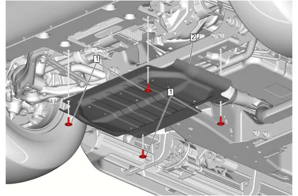
- Underbody Skid Shield Bolt (1) » Remove [4x]
- Underbody Skid Shield (2) » Remove
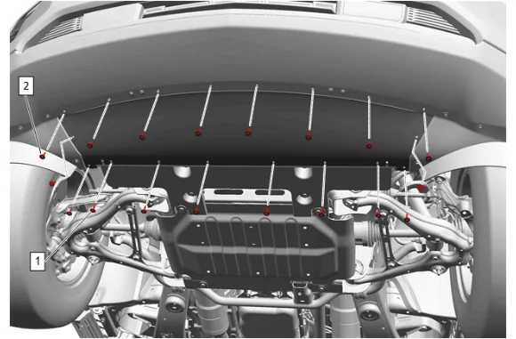
- Front Bumper Fascia Air Deflector Bolt (1) » Remove [10x]
- Front Bumper Fascia Extension Bolt (2) » Remove [8x]
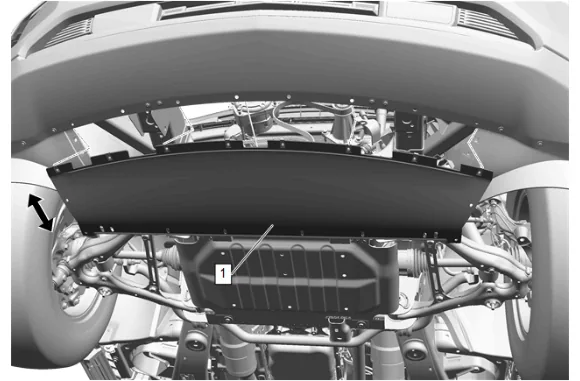
- Pull the front bumper fascia extension (1) rearward and down from the front bumper fascia.
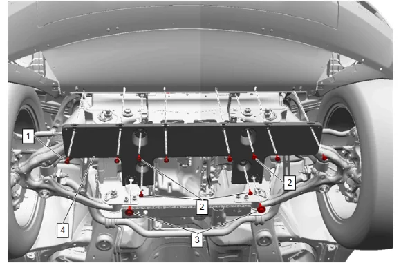
- Front Bumper Fascia Extension Bolt (2) » Remove [4x]
- Pull the front bumper fascia extension (4) rearward and down.
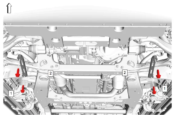
- Front Lower Control Arm Bracket Bolt (1) » Remove [4x]
- Front Lower Control Arm Brace (2) » Remove [2x]
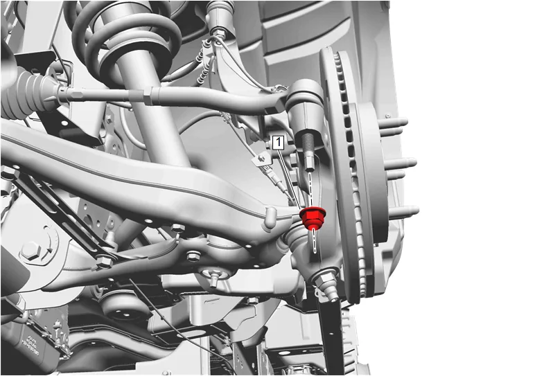
- Remove the left and right steering linkage outer tie rod nuts (1).
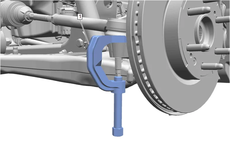
- Using CH-43631 Ball Joint Separator (1), remove the left and right steering linkage outer tie rods from the steering knuckle.
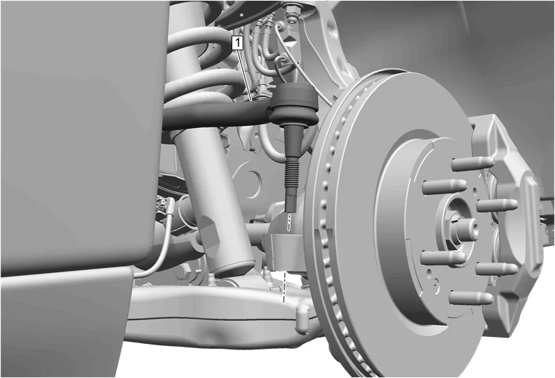
- Separate the left and right steering linkage outer tie rods (1) from the left and right steering knuckles.
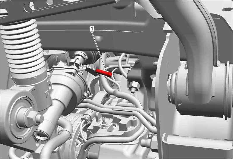
- Intermediate Steering Shaft Lower Bolt (1) » Remove
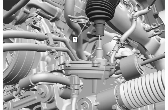
- Intermediate Steering Shaft (1) @ Electric Belt Drive Rack and Pinion Steering Gear » Separate
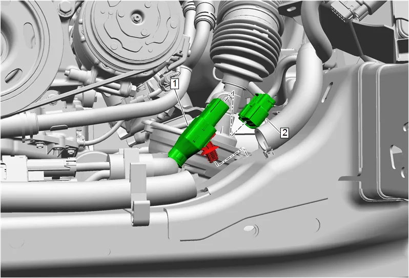
- Remove the power steering wiring harness extension harness (1) from the front suspension crossmember.
- Disconnect the power steering wiring harness extension harness (1) from the chassis main wiring harness (2).
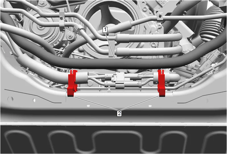
- Remove the chassis main wiring harness (1) from the 2 retaining clips (2) and reposition.
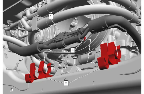
- Remove the power steering assist motor wire clip (3).
- Remove the power steering control module wiring power harness (1) from the 2 retaining clips (2) and reposition.
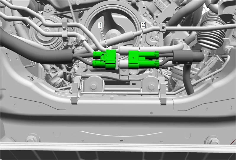
- Disconnect the power steering control module wiring power harness (2) from the main power steering wiring harness (1).
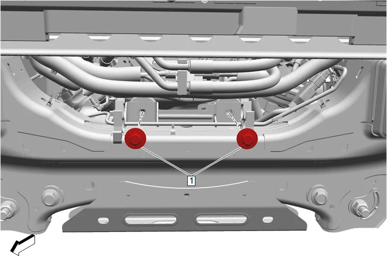
- Steering Gear Bolt - Upper (1) » Remove [2x]
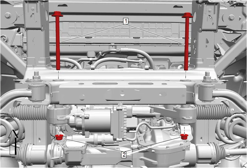
- Steering Gear Nut (2) » Remove [2x]
- Steering Gear Bolt - Lower (1) » Remove [2x]
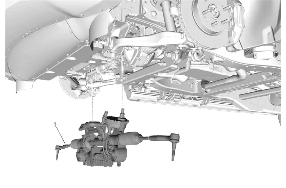
-
Electric Belt Drive Rack and Pinion Steering Gear (1) » Remove Installation Procedure
-
Electric Belt Drive Rack and Pinion Steering Gear (1) » Install
-
Steering Gear Bolt - Lower (1) » Install [2x]
-
Steering Gear Nut (2) » Install [2x]
-
Steering Gear Bolt - Lower (1) » Tighten [2x] — Fastener Specifications
-
Steering Gear Bolt - Upper (1) » Install and tighten [2x] — Fastener Specifications
-
Connect the power steering control module wiring power harness (2) to the main power steering wiring harness (1).
-
Install the power steering assist motor wire clip (3).
-
Position the power steering control module wiring power harness (1) into the 2 retaining clips (2).
-
Position the chassis main wiring harness (1) into the 2 retaining clips (2).
-
Connect the power steering wiring harness extension harness (1) to the chassis main wiring harness (2).
-
Install the power steering wiring harness extension harness (1) to the front suspension crossmember.
-
Intermediate Steering Shaft (1) @ Electric Belt Drive Rack and Pinion Steering Gear » Install
-
If a NEW threaded component is being installed, loosen the adhesive using a metal pick or similar tool before proceeding. If threaded component is reused, prepare the threaded component using the following steps: 13.1. Remove any loose cured adhesive from the external threads of the component using a lint free cloth. 13.2. Thread the cleaned component into the internal mating threads and remove to loosen trapped cured adhesive. 13.3. Apply thread locking adhesive to the external threads of the component. Adhesives, Fluids, Lubricants, and Sealers 13.4. Ensure there are no gaps in the thread locking adhesive once applied to the component.
-
Intermediate Steering Shaft Lower Bolt (1) » Install and tighten — Fastener Specifications
- If reusing the steering linkage outer tie rod (1), add a small amount of grease on the lip of the rubber boot seal to prevent twisting or deforming of the boot. Do NOT apply grease to the ball joint stud. Adhesives, Fluids, Lubricants, and Sealers
- Install left and right steering linkage outer tie rods (1) at the left and right steering knuckles.
-
Install and tighten the left and right steering linkage outer tie rod nuts (1). Fastener Specifications
-
Front Lower Control Arm Brace (2) » Install [2x]
-
Front Lower Control Arm Bracket Bolt (1) » Install and tighten [4x] — Fastener Specifications
-
Front Bumper Fascia Extension (4) » Install
-
Front Bumper Fascia Extension Bolt (2) » Install and tighten [4x] — Fastener Specifications
-
Front Bumper Fascia Extension (1) » Install
-
Front Bumper Fascia Extension Bolt (2) » Install and tighten [8x] — Fastener Specifications
-
Front Bumper Fascia Air Deflector Bolt (1) » Install and tighten [10x] — Fastener Specifications
-
Underbody Skid Shield (2) » Install
-
Underbody Skid Shield Bolt (1) » Install and tighten [4x] — Fastener Specifications
-
Install the front tire and wheel assemblies. Tire and Wheel Removal and Installation
-
Remove the supports and lower the vehicle.
-
Connect the battery negative cable. Battery Negative Cable Disconnection and Connection
-
Measure and adjust the front toe. Wheel Alignment - Steering Wheel Angle and/or Front Toe Adjustment
-
Perform the necessary programming and setup procedure: Control Module References