Engine Coolant Flow Control Valve Replacement
Single Use Fasteners and Components Engine Coolant Thermostat Housing Gasket Oil Level Indicator Tube Seal Removal Procedure
- Disconnect the negative battery cable. Battery Negative Cable Disconnection and Connection
- Secure the steering wheel so it will not turn when the upper intermediate steering shaft and steering column are disconnected.
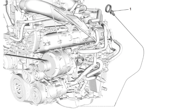
- Engine Oil Level Indicator (1) » Remove
- Drain the cooling system. Cooling System Draining and Filling
- Front Wheelhouse Liner - Left Side » Remove — Front Wheelhouse Liner Replacement
- Lower the vehicle.
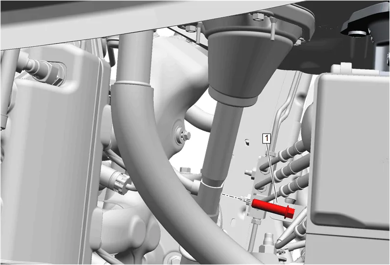
- Mid Intermediate Steering Shaft Bolt (1) » Remove
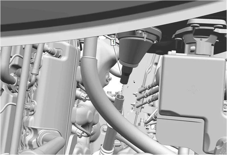
- Upper Intermediate Steering Shaft (1) @ Intermediate Shaft » Separate
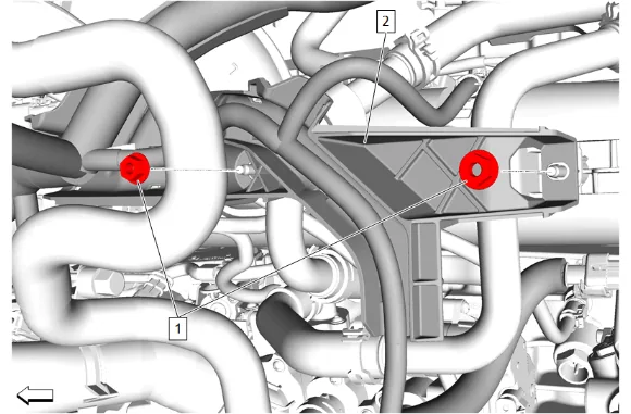
- Engine Wiring Harness Bracket Nut (1) » Remove [2x]
- Engine Wiring Harness Bracket (2) » Reposition
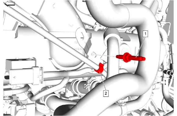
- Oil Level Indicator Tube Stud (1) » Remove
- Clip (2) @ Oil Level Indicator Tube » Remove
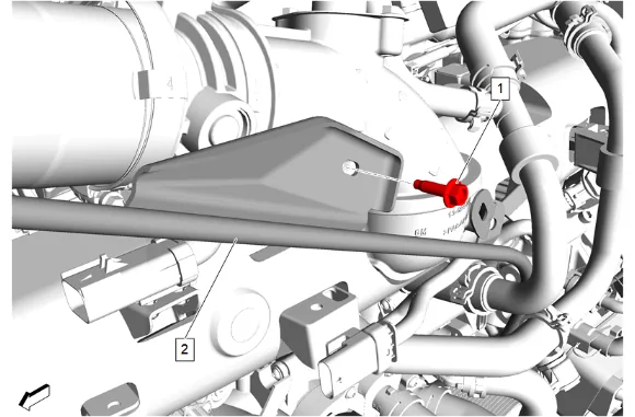
- Oil Level Indicator Tube Bolt (1) » Remove
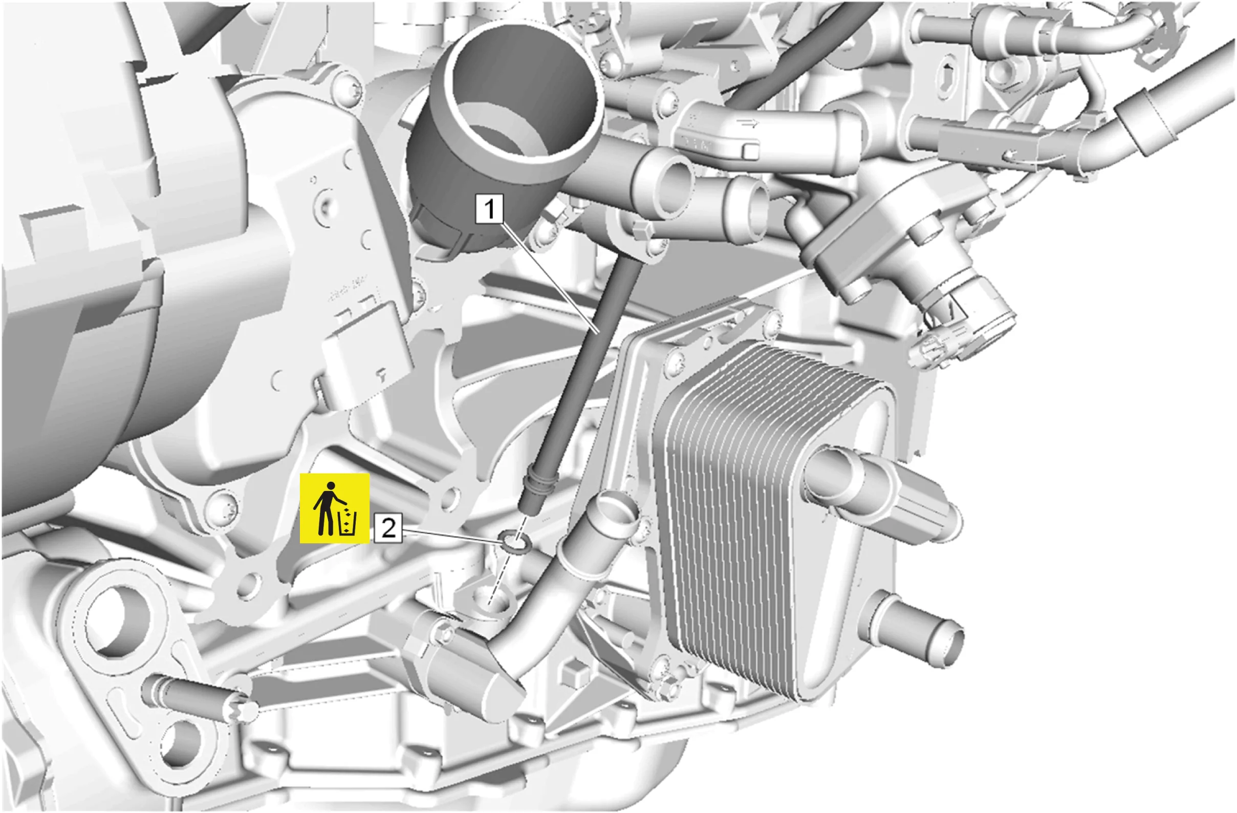
- Oil Level Indicator Tube (1) @ Lower Crankcase Extension » Remove
- Oil Level Indicator Tube Seal (2) » Remove and DISCARD
- Place a drain pan under the engine coolant flow control valve.
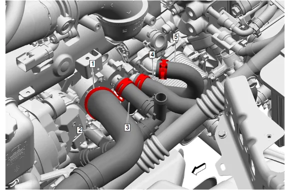
- Hose Clamp (1) » Disengage [4x] — Hose Clamp Replacement Guidelines - Spring Type
- Thermostat Bypass Hose (5) @ Engine Coolant Flow Control Valve » Remove
- Engine Oil Cooler Coolant Inlet Hose (4) @ Engine Coolant Flow Control Valve » Remove
- Thermostat Bypass Hose (3) @ Engine Coolant Flow Control Valve » Remove
- Radiator Inlet Hose (2) @ Engine Coolant Flow Control Valve » Remove
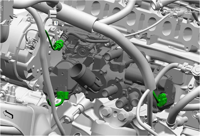
- Reposition hoses and clips as necessary.
- Electrical Connector (1) @ Engine Coolant Flow Control Valve » Disconnect [3x]
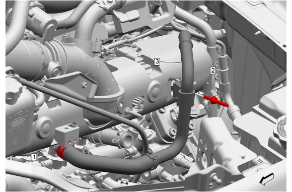
- Hose Clamp (1) » Disengage — Hose Clamp Replacement Guidelines - Spring Type
- Thermostat Bypass Hose (3) » Remove
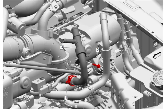
- Hose Clamp (1) » Disengage — Hose Clamp Replacement Guidelines - Spring Type
- Thermostat Bypass Pipe Bolt (2) » Remove
- Exhaust Gas Recirculation Coolant Return Pipe (3) » Remove
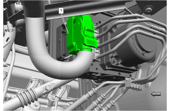
- Disconnect electrical connector (1) at the brake master cylinder and position the harness aside.
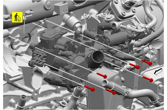
- Engine Coolant Flow Control Valve Bolt (1) » Remove [6x]
- Remove the engine coolant flow control valve (2) through the wheel opening.
- Engine Coolant Thermostat Housing Gasket (3) » Remove and DISCARD
- Remove the drain pan.
- Transfer components as necessary. Cleaning and Inspection Procedure - Conditional
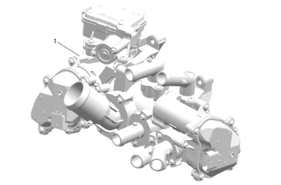
-
Clean the engine coolant flow control valve (1).
-
Inspect the engine coolant flow control valve (1).
-
Replace the engine coolant flow control valve (1) if any damage is found. Installation Procedure
-
Clean the sealing surface of the engine block.
-
Engine Coolant Thermostat Housing Gasket (3) » Install NEW
-
Install the engine coolant flow control valve (2) through the wheel opening.
-
Engine Coolant Flow Control Valve Bolt (1) » Install and tighten [6x] — Fastener Specifications
-
To aid in installation, route the oil level indicator tube into position but do not install it to the lower crankcase extension at this time.
-
Oil Level Indicator Tube Seal (2) @ Oil Level Indicator Tube » Install NEW
-
Oil Level Indicator Tube (1) @ Lower Crankcase Extension » Install
-
Position the wiring harness into place and connect electrical connector (1) at the brake master cylinder.
-
Electrical Connector (1) @ Engine Coolant Flow Control Valve » Connect [3x]
-
Install the hoses and clips as necessary.
-
Exhaust Gas Recirculation Coolant Return Pipe (3) » Install
-
Thermostat Bypass Pipe Bolt (2) » Install and tighten — Fastener Specifications
-
Hose Clamp (1) » Engage — Hose Clamp Replacement Guidelines - Spring Type
-
Thermostat Bypass Hose (3) » Install
-
Hose Clamp (1) » Engage — Hose Clamp Replacement Guidelines - Spring Type
-
Radiator Inlet Hose (2) @ Engine Coolant Flow Control Valve » Install
-
Thermostat Bypass Hose (3) @ Engine Coolant Flow Control Valve » Install
-
Engine Oil Cooler Coolant Inlet Hose (4) @ Engine Coolant Flow Control Valve » Install
-
Thermostat Bypass Hose (5) @ Engine Coolant Flow Control Valve » Install
-
Hose Clamp (1) » Engage [4x] — Hose Clamp Replacement Guidelines - Spring Type
-
Oil Level Indicator Tube Bolt (1) » Install and tighten — Fastener Specifications
-
Clip (2) @ Oil Level Indicator Tube » Install
-
Oil Level Indicator Tube Stud (1) » Install and tighten — Fastener Specifications
-
Engine Wiring Harness Bracket (2) » Install
-
Engine Wiring Harness Bracket Nut (1) » Install and tighten [2x] — Fastener Specifications
-
Upper Intermediate Steering Shaft (1) @ Intermediate Shaft » Install
-
If a NEW threaded component is being installed, loosen the adhesive using a metal pick or similar tool before proceeding. If threaded component is reused, prepare the threaded component using the following steps: 27.1. Remove any loose cured adhesive from the external threads of the component using a lint free cloth. 27.2. Thread the cleaned component into the internal mating threads and remove to loosen trapped cured adhesive. 27.3. Apply thread locking adhesive to the external threads of the component. Adhesives, Fluids, Lubricants, and Sealers 27.4. Ensure there are no gaps in the thread locking adhesive once applied to the component.
-
Mid Intermediate Steering Shaft Bolt (1) » Install and tighten — Fastener Specifications
-
Front Wheelhouse Liner - Left Side » Install — Front Wheelhouse Liner Replacement
-
Install the negative battery cable to the battery. Battery Negative Cable Disconnection and Connection
-
Remove the device used to prevent steering column rotation.
-
Fill the cooling system. Cooling System Draining and Filling
-
Engine Oil Level Indicator (1) » Install
-
Start the engine and check for leaks.