Intake Manifold Replacement
Single Use Fasteners and Components Exhaust Gas Recirculation Cooler Inlet Pipe Gasket Exhaust Gas Recirculation Pipe Seal Intake Manifold Gasket [6x] Oil Level Indicator Tube Seal Throttle Body Gasket Removal Procedure
- Plenum Front Panel Outer Reinforcement » Remove — Plenum Front Panel Outer Reinforcement Removal and Installation
- Drain the cooling system. Cooling System Draining and Filling
- Front Wheelhouse Liner - Left Side » Remove — Front Wheelhouse Liner Replacement
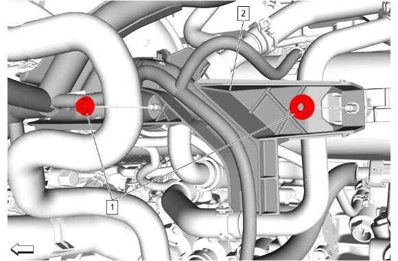
- Engine Wiring Harness Bracket Nut (1) » Remove [2x]
- Engine Wiring Harness Bracket (2) » Reposition
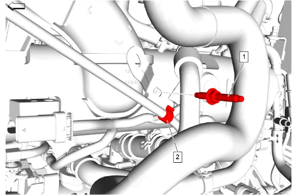
- Oil Level Indicator Tube Stud (1) » Remove
- Clip (2) @ Oil Level Indicator Tube » Remove
- Oil Filler Cap » Remove
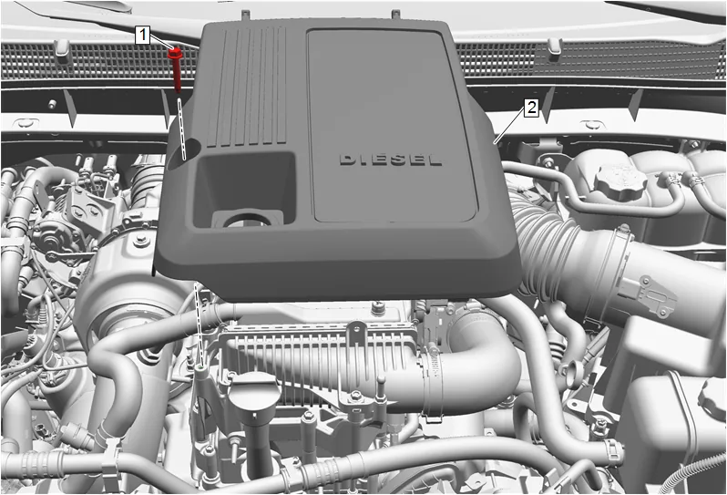
- Intake Manifold Cover Bolt (1) » Remove
- Intake Manifold Cover (2) » Remove
- Install the oil filler cap after removal of the intake manifold cover to prevent debris from falling into the engine.
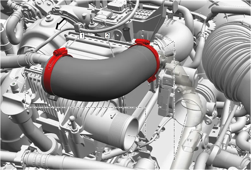
- Charge Air Cooler Outlet Air Hose Clamp (1) » Loosen until disengaged [2x]
- Charge Air Cooler Outlet Air Hose (2) » Remove
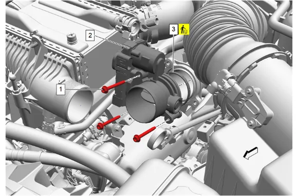
- Disconnect the throttle body electrical connector.
- Throttle Body Bolt (1) » Remove [3x]
- Throttle Body (2) » Remove
- Throttle Body Gasket (3) » Remove and DISCARD
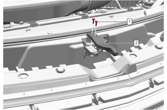
- Hood Latch Actuator Bolt (1) » Remove [2x]
- Hood Secondary Latch Release Handle (2) » Remove
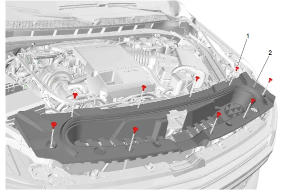
- Intake Air Baffle Retainer (1) » Remove [9x]
- Intake Air Splash Shield (2) » Remove
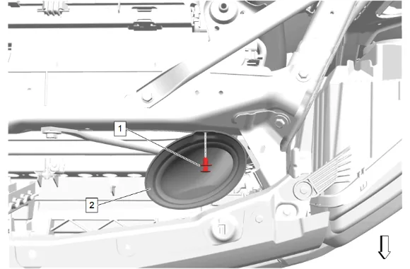
- Intake Air Duct Retainer (1) » Remove
- Intake Air Duct (2) » Reposition
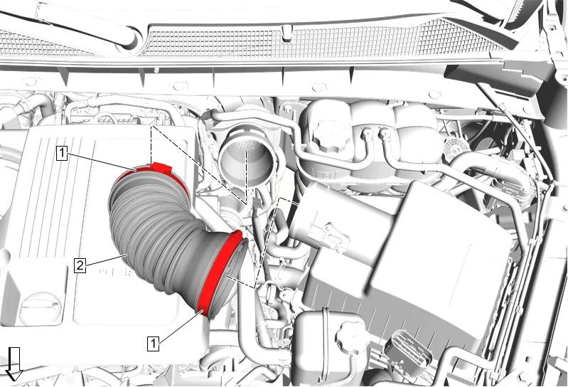
- Air Cleaner Outlet Duct Clamp (1) » Loosen [2x]
- Air Cleaner Outlet Front Duct (2) » Remove
- Disconnect the mass airflow sensor electrical connector.
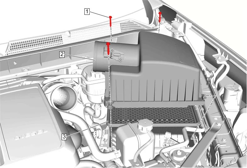
- Air Cleaner Housing Cover Bolt (1) » Remove [3x]
- Air Cleaner Upper Housing (2) » Remove
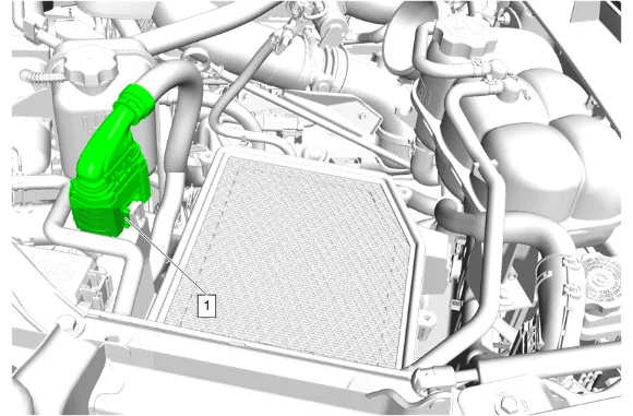
- Electrical Connector (1) @ Air Cleaner Lower Housing » Remove
- Remove all retainers from air cleaner lower housing.
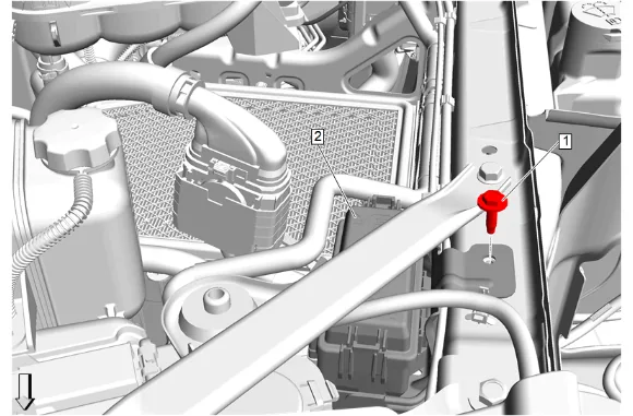
- Engine Wiring Harness Fuse Block Bracket Bolt (1) » Remove
- Accessory Wiring Junction Block (2) » Reposition
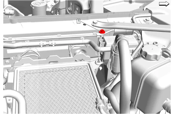
- Air Cleaner Nut (1) » Remove
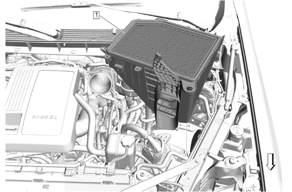
- Air Cleaner Lower Housing (1) » Remove
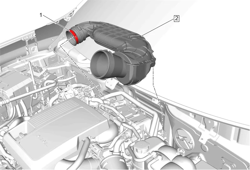
- Air Cleaner Outlet Duct Clamp (1) » Loosen
- Air Cleaner Outlet Duct (2) » Remove
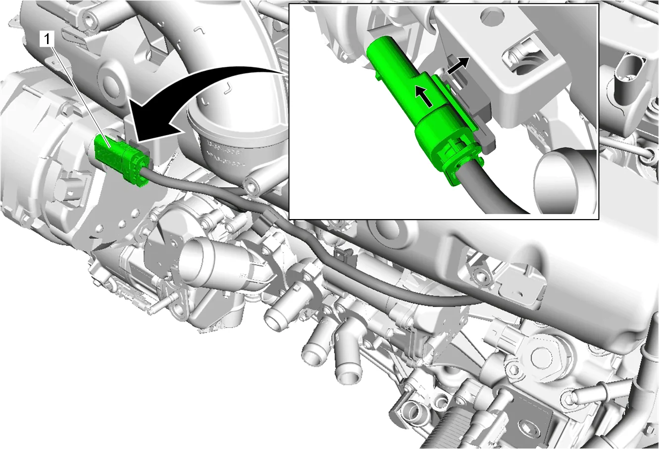
- Unclip the engine coolant temperature sensor wiring harness (1) from the intake manifold.
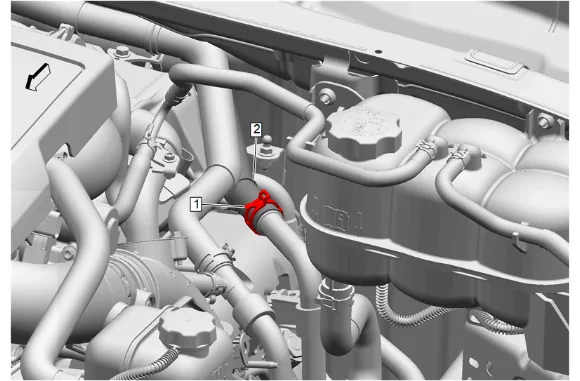
- Hose Clamp (1) » Disengage — Hose Clamp Replacement Guidelines - Spring Type
- Exhaust Gas Recirculation Cooler Water Bypass Inlet Hose (2) @ Thermostat Bypass Hose » Remove
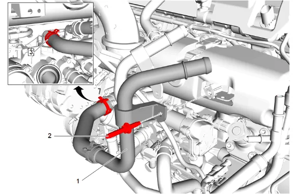
- Engine Coolant Air Bleed Hose Stud (2) » Remove
- Thermostat Bypass Hose (1) » Reposition
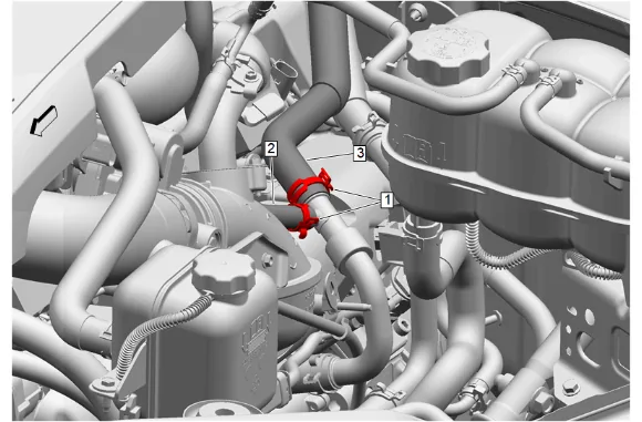
- Hose Clamp (1) » Disengage [2x] — Hose Clamp Replacement Guidelines - Spring Type
- Turbocharger Coolant Return Hose (2) @ Exhaust Gas Recirculation Coolant Return Pipe » Remove
- Exhaust Gas Recirculation Coolant Return Pipe (3) @ Exhaust Gas Recirculation Coolant Return Pipe » Remove
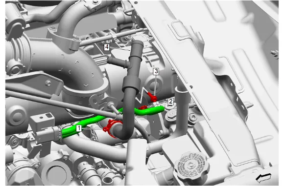
- Thermostat Bypass Pipe Bolt (3) » Remove
- Hose Clamp (1) » Disengage — Hose Clamp Replacement Guidelines - Spring Type
- Wiring Harness Retainer (2) @ Exhaust Gas Recirculation Coolant Return Pipe » Remove
- Exhaust Gas Recirculation Coolant Return Pipe (4) » Remove
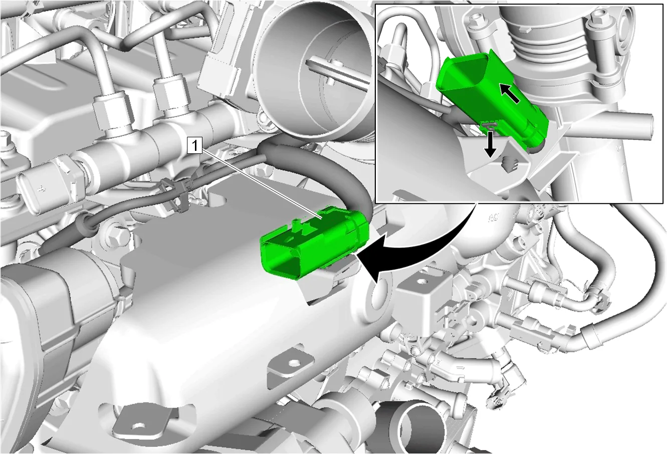
- Disconnect and unclip the glow plug wiring harness (1) from the intake manifold.
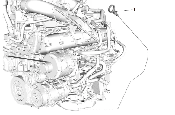
- Engine Oil Level Indicator (1) » Remove
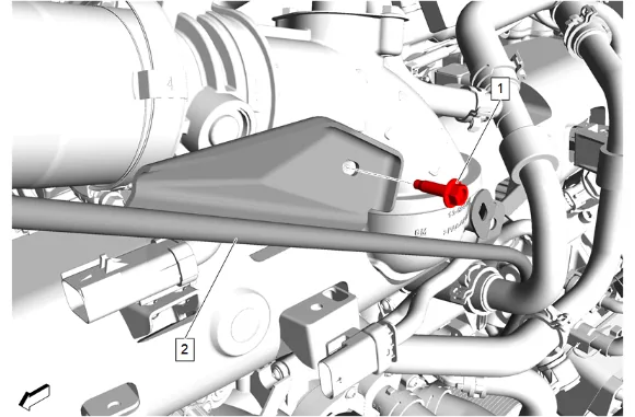
- Oil Level Indicator Tube Bolt (1) » Remove
- Oil Level Indicator Tube (2) » Remove
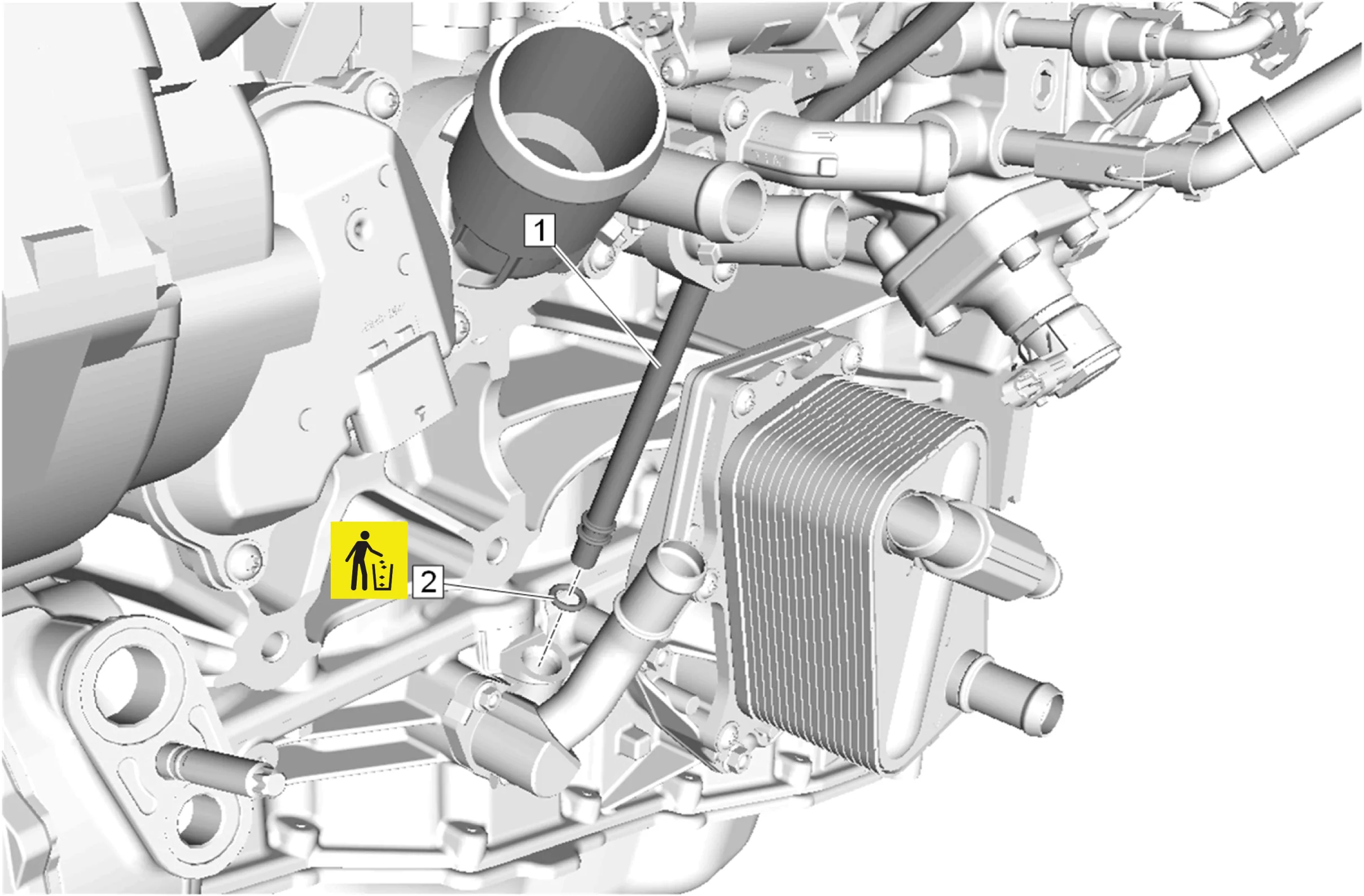
- Oil Level Indicator Tube Seal (2) » Remove and DISCARD
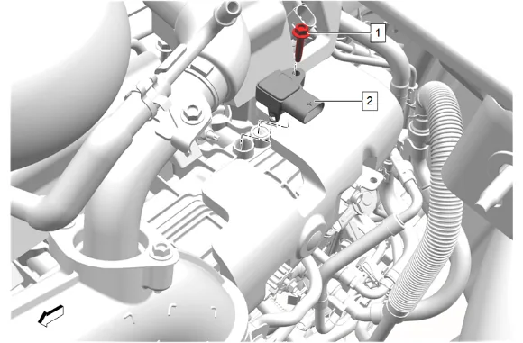
- Disconnect the intake air pressure and temperature sensor electrical connector.
- Intake Air Pressure and Temperature Sensor Bolt (1) » Remove
- Intake Air Pressure and Temperature Sensor (2) » Remove
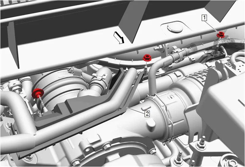
- Remove the 3 rear engine wiring harness channel nuts (1).
- Position the rear engine wiring harness channel (2) out of the way.
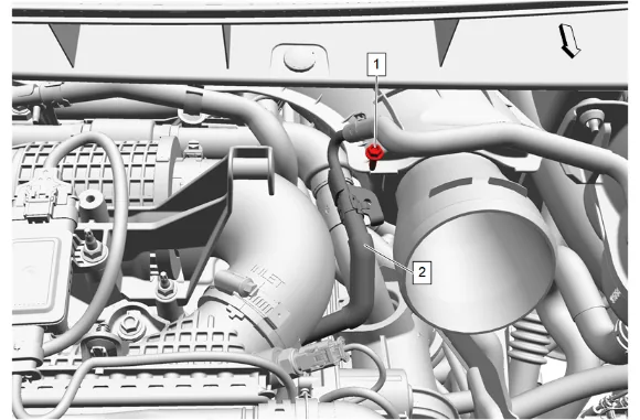
- Remove the engine coolant outlet pipe bracket bolt (1) and position the engine coolant air bleed hose (2) out of the way.
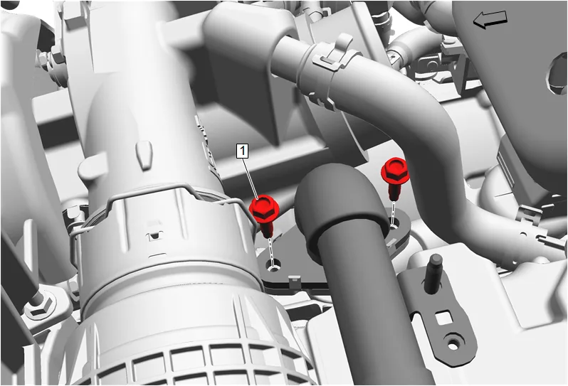
- Exhaust Gas Recirculation Cooler Bolt (1) » Remove [2x]
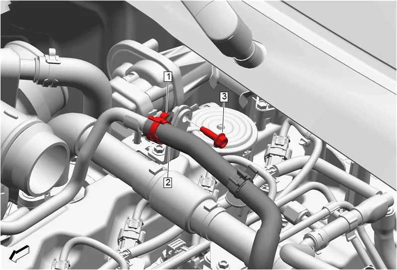
- Hose Clamp (1) » Disengage — Hose Clamp Replacement Guidelines - Spring Type
- Turbocharger Coolant Return Hose (2) @ Turbocharger Coolant Feed Pipe » Remove
- Turbocharger Coolant Feed and Return Pipe Bolt (3) » Remove
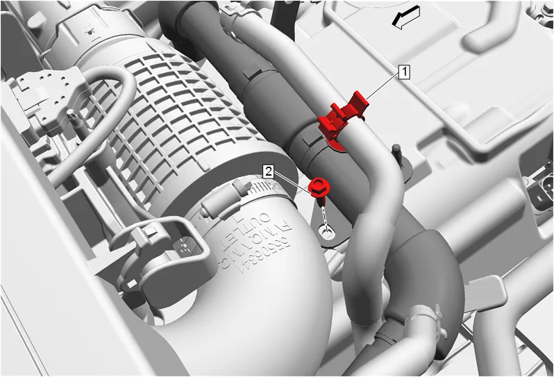
- Remove the turbocharger coolant return hose clip (1) and position the turbocharger coolant return hose out of the way.
- Exhaust Gas Recirculation Outlet Pipe Bolt (2) » Remove
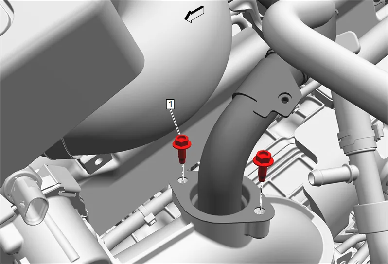
- Exhaust Gas Recirculation Outlet Pipe Bolt (1) » Remove [2x]
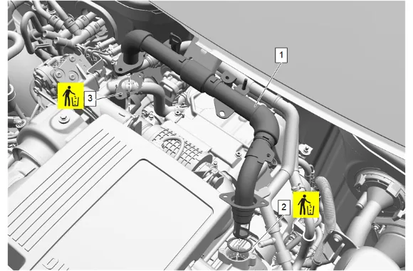
- Remove the exhaust gas recirculation pipe (1).
- Remove and DISCARD the exhaust gas recirculation pipe seal (2).
- Remove and DISCARD the exhaust gas recirculation cooler inlet pipe gasket (3).
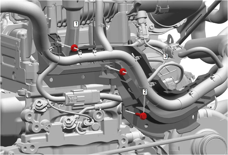
- Engine Wiring Harness Bracket Nut (1) » Remove [2x]
- Engine Wiring Harness Bracket Bolt (2) » Remove
- Disconnect electrical connectors as needed, detach retainer at intake manifold and reposition the engine wiring harness channel (3) away from the front of the engine.
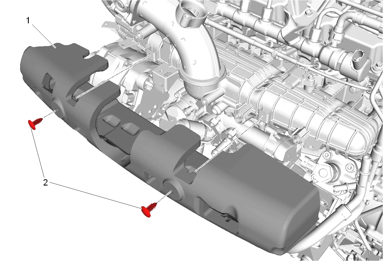
- Intake Manifold Insulator Retainer (2) » Remove [2x]
- Intake Manifold Insulator (1) » Remove
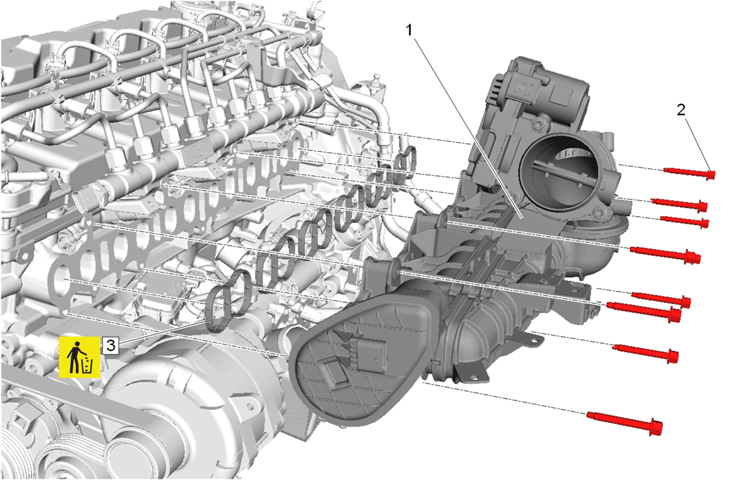
- Intake Manifold Bolt (2) » Remove [9x]
- Intake Manifold (1) » Remove
- Intake Manifold Gasket (3) » Remove and DISCARD [6x] Cleaning and Inspection Procedure - Required
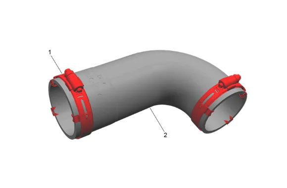
- Inspect the charge air cooler outlet air hose (2): 1.1. Use dish soap and water to clean the inside of the charge air cooler outlet air hose (2). Clean the interior of the hose, and allow to completely dry. Ensure any oil residue is removed from the hose internal interface surfaces. 1.2. Inspect the interior of the charge air cooler outlet air hose (2) for tears or delamination. Replace the hose if damage is found. 1.3. Inspect the charge air cooler outlet air hose clamps (1). Replace the charge air cooler outlet air hose (2) if damage is found or the clamp components are missing. Cleaning and Inspection Procedure - Conditional
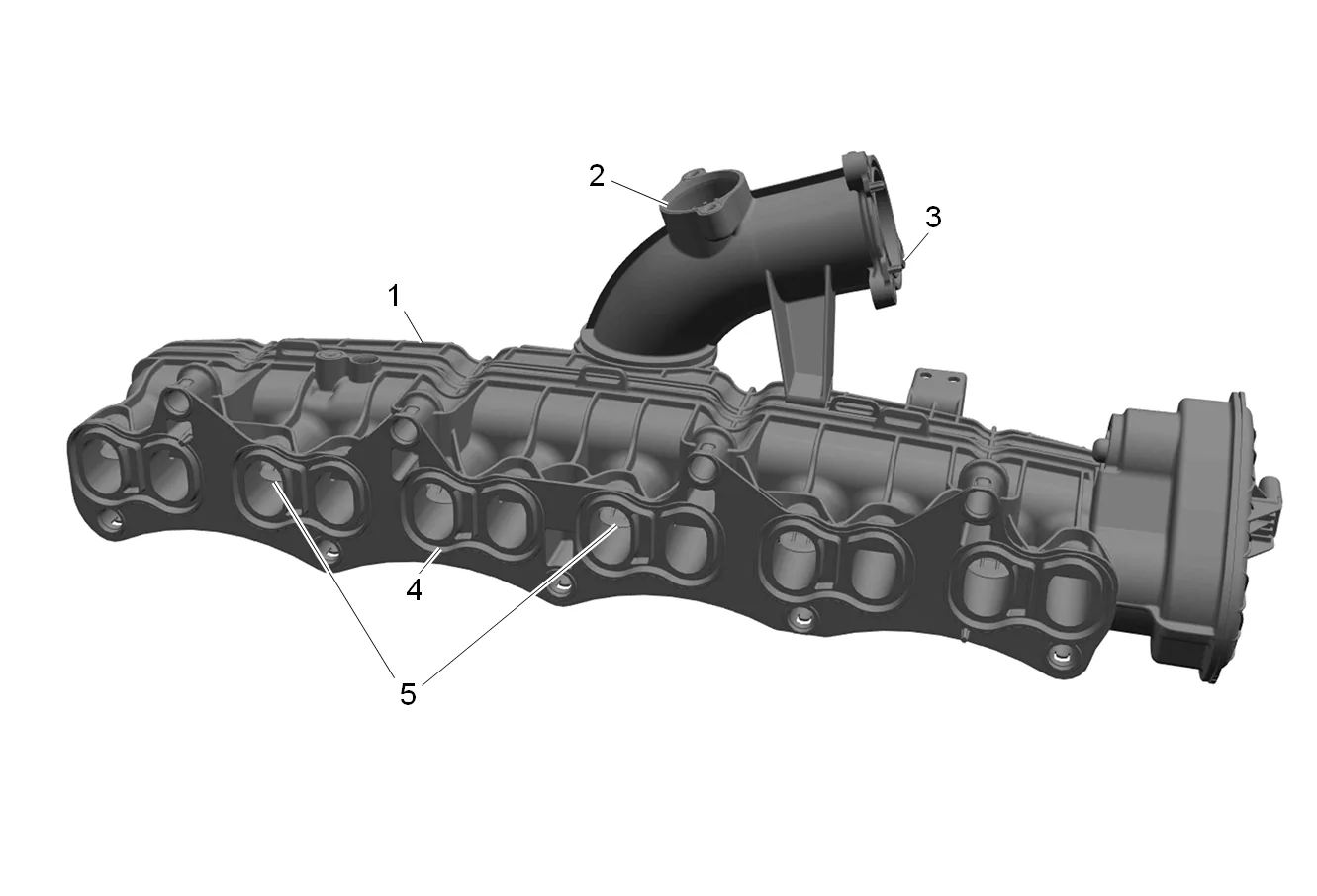
- Clean the intake manifold mating surfaces.
- Inspect the intake manifold (1) for damage.
- Inspect the intake manifold (1) for cracks and fractures.
- Inspect all 12 intake runner valves (5) for damage.
- Clean the throttle body sealing surface (3).
- Clean the exhaust gas recirculation cooler outlet pipe sealing surface (2).
- Clean the intake manifold to cylinder head sealing surface (4).
- Replace the intake manifold (1) as necessary.
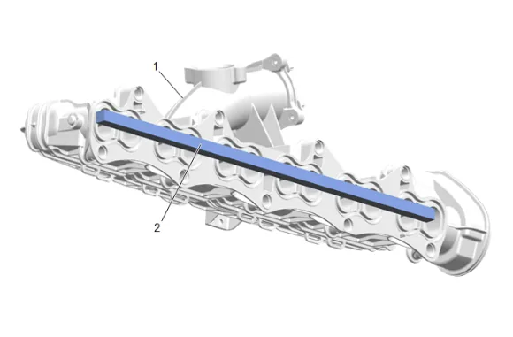
-
Visually inspect the intake manifold mounting face (1) for cracks, warpage, or damage. If any damage is found replace the intake manifold. An intake manifold face with cracks, warpage or damage may cause an intake leak and may effect diagnostics and system performance. Installation Procedure
-
Intake Manifold Gasket (3) » Install NEW [6x]
-
Intake Manifold (1) » Install
-
Intake Manifold Bolt (2) » Install and hand tighten [9x]
-
Intake Manifold Bolt (2) » Tighten in sequence [9x] — Fastener Specifications
-
Intake Manifold Insulator (1) » Install
-
Intake Manifold Insulator Retainer (2) » Install [2x]
-
Position the engine wiring harness channel (3) at the front of the engine, attach retainer at intake manifold, and connect electrical connectors as needed .
-
Engine Wiring Harness Bracket Bolt (2) » Install and tighten — Fastener Specifications
-
Engine Wiring Harness Bracket Nut (1) » Install and tighten [2x] — Fastener Specifications
-
Install a NEW exhaust gas recirculation cooler inlet pipe gasket (3).
-
Install a NEW exhaust gas recirculation pipe seal (2).
-
Install the exhaust gas recirculation pipe (1).
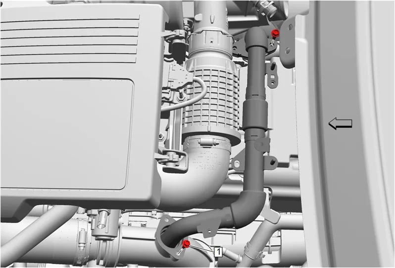
-
Install and hand tighten the 2 exhaust gas recirculation pipe bolts (1).
-
Turbocharger Coolant Feed and Return Pipe Bolt (3) » Install and tighten — Fastener Specifications
-
Turbocharger Coolant Return Hose (2) @ Turbocharger Coolant Feed Pipe » Install
-
Hose Clamp (1) » Engage — Hose Clamp Replacement Guidelines - Spring Type
-
Exhaust Gas Recirculation Outlet Pipe Bolt (1) » Install and tighten [2x] — Fastener Specifications.
-
Exhaust Gas Recirculation Outlet Pipe Bolt (2) » Install and tighten — Fastener Specifications
-
Install the turbocharger coolant return hose clip (1).
-
Exhaust Gas Recirculation Cooler Bolt (1) » Install and tighten [2x] — Fastener Specifications.
-
Engine Coolant Air Bleed Hose (2) » Reposition
-
Engine Coolant Outlet Pipe Bracket Bolt (1) » Install and tighten — Fastener Specifications
-
Install the rear engine wiring harness channel (2).
-
Engine Wiring Harness Bracket Nut (1) » Install and tighten [3x] — Fastener Specifications.
-
Intake Air Pressure and Temperature Sensor (2) » Install
-
Intake Air Pressure and Temperature Sensor Bolt (1) » Install and tighten — Fastener Specifications
-
Connect the intake air pressure and temperature sensor electrical connector.
-
Oil Level Indicator Tube Seal (2) @ Oil Level Indicator Tube » Install NEW
-
Oil Level Indicator Tube (1) @ Lower Crankcase Extension » Install
-
Oil Level Indicator Tube (2) » Install
-
Oil Level Indicator Tube Bolt (1) » Install and tighten — Fastener Specifications
-
Engine Oil Level Indicator (1) » Install
-
Connect electrical connector and clip the glow plug wiring harness (1) to the intake manifold.
-
Clip the engine coolant temperature sensor wiring harness (1) to the intake manifold.
-
Exhaust Gas Recirculation Coolant Return Pipe (4) » Install
-
Hose Clamp (1) » Engage — Hose Clamp Replacement Guidelines - Spring Type
-
Thermostat Bypass Pipe Bolt (3) » Install and tighten — Fastener Specifications
-
Wiring Harness Retainer (2) @ Exhaust Gas Recirculation Coolant Return Pipe » Install
-
Exhaust Gas Recirculation Coolant Return Pipe (3) @ Exhaust Gas Recirculation Coolant Return Pipe » Install
-
Turbocharger Coolant Return Hose (2) @ Exhaust Gas Recirculation Coolant Return Pipe » Install
-
Hose Clamp (1) » Engage [2x] — Hose Clamp Replacement Guidelines - Spring Type
-
Thermostat Bypass Hose (1) » Install
-
Engine Coolant Air Bleed Hose Stud (2) » Install and tighten — Fastener Specifications
-
Exhaust Gas Recirculation Cooler Water Bypass Inlet Hose (2) @ Thermostat Bypass Hose » Install
-
Hose Clamp (1) » Engage — Hose Clamp Replacement Guidelines - Spring Type
-
Air Cleaner Outlet Duct (2) » Install
-
Air Cleaner Outlet Duct Clamp (1) » Tighten — Fastener Specifications
-
Air Cleaner Lower Housing (1) » Install
-
Air Cleaner Nut (1) » Install and tighten — Fastener Specifications
-
Accessory Wiring Junction Block (2) » Install
-
Engine Wiring Harness Fuse Block Bracket Bolt (1) » Install and tighten — Fastener Specifications
-
Electrical Connector (1) @ Air Cleaner Lower Housing » Install
-
Install all retainers to the air cleaner lower housing.
-
Air Cleaner Upper Housing (2) » Install
-
Air Cleaner Housing Cover Bolt (1) » Install and tighten [3x] — Fastener Specifications
-
Connect the mass airflow sensor electrical connector.
-
Intake Air Duct (2) » Install
-
Intake Air Duct Retainer (1) » Install
-
Intake Air Splash Shield (2) » Install
-
Intake Air Baffle Retainer (1) » Install [9x]
-
Hood Secondary Latch Release Handle (2) » Install
-
Hood Latch Actuator Bolt (1) » Install and tighten [2x] — Fastener Specifications
-
Throttle Body Gasket (3) » Install NEW
-
Throttle Body (2) » Install
-
Throttle Body Bolt (1) » Install and tighten [3x] — Fastener Specifications
-
Connect the throttle body electrical connector.
-
Charge Air Cooler Outlet Air Hose (2) » Install
-
Charge Air Cooler Outlet Air Hose Clamp (1) » Tighten [2x] — Fastener Specifications
-
Clip (2) @ Oil Level Indicator Tube » Install
-
Oil Level Indicator Tube Stud (1) » Install and tighten — Fastener Specifications
-
Engine Wiring Harness Bracket (2) » Install
-
Engine Wiring Harness Bracket Nut (1) » Install and tighten [2x] — Fastener Specifications
-
Front Wheelhouse Liner - Left Side » Install — Front Wheelhouse Liner Replacement
-
Plenum Front Panel Outer Reinforcement » Install — Plenum Front Panel Outer Reinforcement Removal and Installation
-
Oil Filler Cap » Remove
-
Intake Manifold Cover (2) » Install
-
Intake Manifold Cover Bolt (1) » Install and tighten — Fastener Specifications
-
Oil Filler Cap » Install
-
Fill the cooling system to the proper level. Cooling System Draining and Filling
-
Start the engine and check for coolant leaks.