Valve Stem Oil Seal and Valve Spring Replacement - Left Side (L84)
Valve Stem Oil Seal and Valve Spring Replacement - Left Side (L84) Single Use Fasteners and Components Valve Rocker Arm Cover Gasket Exhaust Valve Stem Oil Seal Intake Valve Stem Oil Seal Special Tools EN-22794 Spark Plug Port Adapter EN-46116 Valve Stem Seal Remover/Installer EN-46335-A Valve Spring Compressor-Head On-Vehicle Equivalent regional tools: Special Tools Removal Procedure
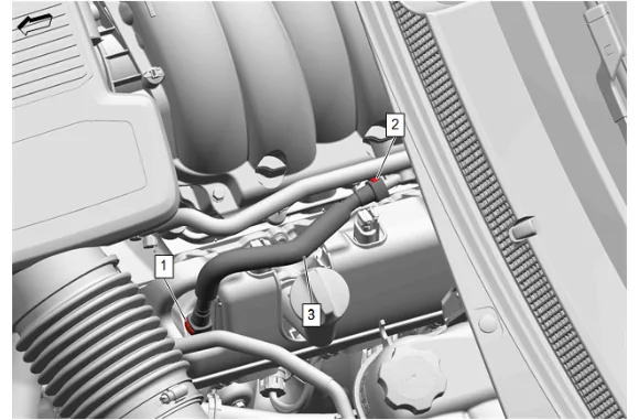
- Positive Crankcase Ventilation Tube Connector (1) @ Positive Crankcase Ventilation Fitting » Disconnect — Plastic Collar Quick Connect Fitting Service
- Positive Crankcase Ventilation Tube Connector (2) @ Intake Manifold » Disconnect — Plastic Collar Quick Connect Fitting Service
- Positive Crankcase Ventilation Foul Air Tube (3) » Remove
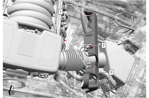
- Grasp the valve rocker arm cover insulator (3) and lift up disengaging the 3 upper intake manifold sight shield grommets (2) from the 3 valve rocker arm cover insulator retainers (1).
- Valve Rocker Arm Cover Insulator (3) » Remove
- Inspect the 3 upper intake manifold sight shield grommets (2) on the valve rocker arm cover insulator and replace as necessary.
- Engine Wiring Harness » Reposition
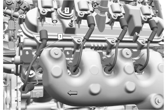
- Twist the 4 spark plug wire boots a ½ turn and remove the 4 spark plug wires (1) from the 4 ignition coils (2).
- Inspect the 4 spark plug wire for damage and replace if necessary.
- Engine Wiring Harness Connector @ Ignition Coil » Disconnect [4x]
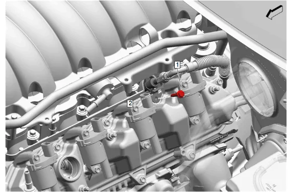
- Fuel Feed Pipe Bolt (1) @ Fuel Feed Pipe (2) » Remove
- Fuel Feed Pipe (2) » Reposition
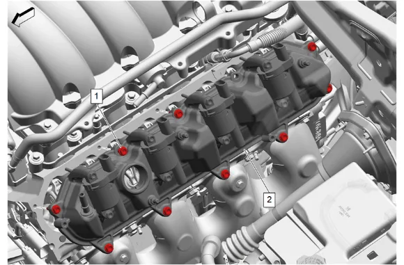
- Valve Rocker Arm Cover Bolt (1) » Loosen until disengaged [9x]
- Valve Rocker Arm Cover - Left Side (2) » Remove
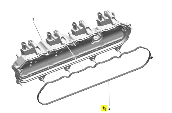
- Valve Rocker Arm Cover Gasket (2) @ Valve Rocker Arm Cover (1) » Remove and DISCARD
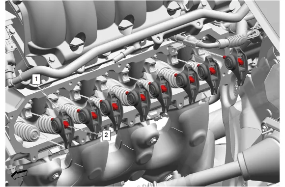
- Valve Rocker Arm Pivot Support Bolt (2) » Loosen until disengaged
- Valve Rocker Arm (1) » Remove
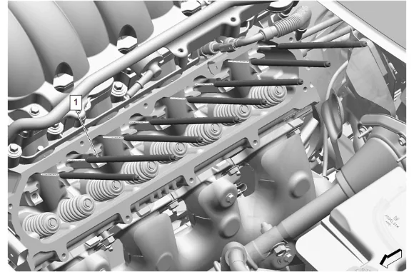
- Valve Push Rod (1) » Remove
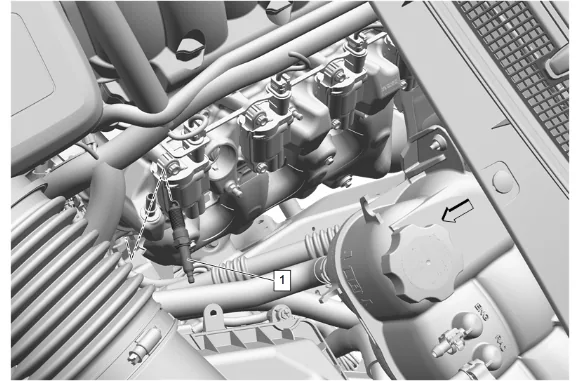
- Loosen the applicable gas engine ignition spark plug 1 or 2 turns.
- Use a brush, or compressed air in order to remove any dirt from the gas engine ignition spark plugs.
- Remove the gas engine ignition spark plug (1) from the applicable cylinder.
- If reusing the gas engine ignition spark plug (1), inspect for wear or damage.
- Install the EN-22794 Spark Plug Port Adapter to the applicable cylinder.
- Connect the EN-22794 Spark Plug Port Adapter to a compressed air source.
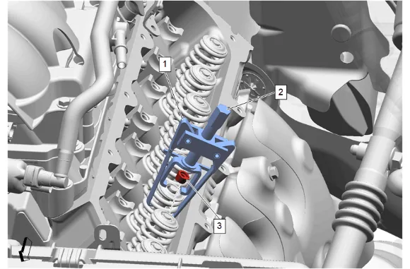
- EN-46335-A Valve Spring Compressor-Head On-Vehicle (1) » Install
- Tighten the EN-46335-A Valve Spring Compressor-Head On-Vehicle (2) to release the valve stem key (3).
- Valve Stem Key (3) » Remove
- Loosen the EN-46335-A Valve Spring Compressor-Head On-Vehicle (2) and remove the compressor.
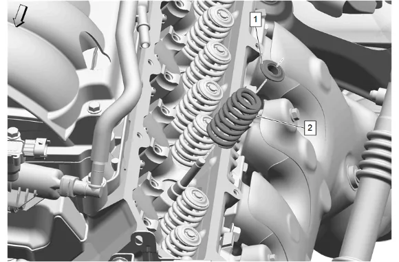
- Valve Spring Cap (1) » Remove
- Valve Spring (2) » Remove
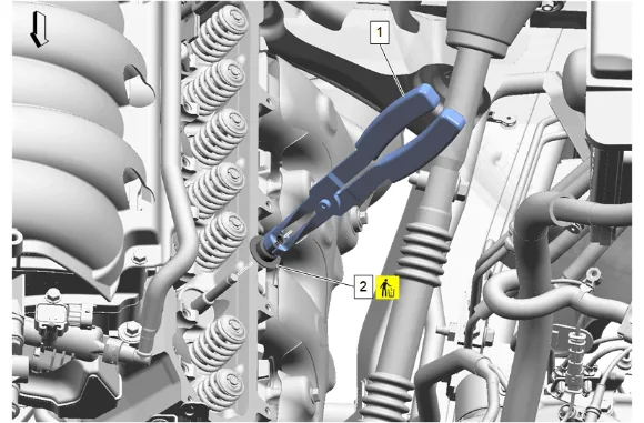
- Use the EN-46116 Valve Stem Seal Remover/Installer (1) to remove and DISCARD the valve stem oil seal (2).
- Using the appropriate tool, clean and prepare the applicable sealing surface. Cleaning and Inspection Procedure - Conditional
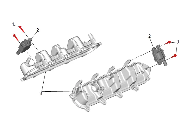
- Remove the 8 ignition coil bolts (1) and 4 ignition coils (2) before cleaning the valve rocker arm cover (3) in solvent. Do NOT submerge the 4 ignition coils (2) in solvent.
- Inspect the valve rocker arm cover (3) for the following conditions: 2.1. Scoring or damage to the gasket surfaces 2.2. Ventilation system passages for restrictions 2.3. Threaded bolt holes for damage or debris
- Install the 4 ignition coils (2).
- Install and tighten the 8 ignition coil bolts (1). Fastener Specifications
- Mark, sort, or organize the components for assembly.
- Clean the components with cleaning solvent.
- Dry the components with compressed air.
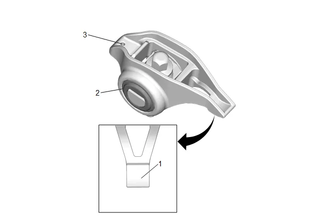
- Inspect the valve rocker arms bearings (2) for binding or roughness.
- Inspect the valve rocker arm pushrod sockets (3) and valve stem mating surfaces (1). These surfaces should be smooth with no scoring or exceptional wear.
- Inspect the pushrods for worn or scored ends. These surfaces should be smooth with no scoring or exceptional wear.
- Inspect the pushrods for bends. Roll the pushrod on a flat surface to determine if the pushrod is bent.
- Inspect the pushrod oil passages for restrictions.
- Inspect the rocker arm pivot supports for cracks, wear, or other damage.
- Inspection the spark plug wire for the following conditions: 14.1. Correct routing of the spark plug wires. Incorrect routing may cause cross-firing. 14.2. Inspect for any signs of cracks or splits in the wires.
- Inspect each boot for the following conditions: 15.1. Tearing 15.2. Piercing 15.3. Arcing 15.4. Carbon tracking 15.5. Corroded terminals
- If corrosion, carbon tracking or arcing are indicated on a spark plug wire boot or on a terminal, replace the wire and the component connected to the wire. Installation Procedure
-
Using the EN-46116 Valve Stem Seal Remover/Installer (1) install the NEW valve stem oil seal (2).
-
Valve Spring (2) » Install
-
Valve Spring Cap (1) » Install
-
EN-46335-A Valve Spring Compressor-Head On-Vehicle (1) » Install
-
EN-46335-A Valve Spring Compressor-Head On-Vehicle (2) » Tighten
-
Valve Stem Key (3) » Install
-
Loosen and remove the EN-46335-A Valve Spring Compressor-Head On-Vehicle (2).
-
Disconnect the EN-22794 Spark Plug Port Adapter from the compressed air source.
-
Remove the EN-22794 Spark Plug Port Adapter from the applicable cylinder.
-
Install and tighten the gas engine ignition spark plug (1) to the applicable cylinder. Fastener Specifications
-
Lubricate the flange of the valve rocker arm bolts with clean engine oil. Adhesives, Fluids, Lubricants, and Sealers
-
Lubricate the valve rocker arms and push rods with clean engine oil. Adhesives, Fluids, Lubricants, and Sealers
- Valve Push Rod (1) » Install
- Valve Rocker Arm (1) » Install
-
Valve Rocker Arm Pivot Support Bolt (2) » Install and tighten — Fastener Specifications
-
Valve Rocker Arm Cover Gasket (2) @ Valve Rocker Arm Cover (1) » Install NEW
-
Valve Rocker Arm Cover - Left Side (2) » Install
-
Valve Rocker Arm Cover Bolt (1) » Hand tighten [9x]
-
Fuel Feed Pipe (2) » Reposition
-
Fuel Feed Pipe Bolt (1) @ Fuel Feed Pipe (2) » Install and hand tighten
-
Valve Rocker Arm Cover Bolt (1) » Tighten in sequence [9x] — Fastener Specifications
-
Fuel Feed Pipe Bolt (1) @ Fuel Feed Pipe (2) » Tighten — Fastener Specifications
-
Engine Wiring Harness Connector @ Ignition Coil » Connect [4x]
-
Inspect the inside of the spark plug rubber boots for a thin, even coat of grease. If there is no grease present or additional grease is necessary, apply a thin coating of dielectric grease evenly to the inside of the spark plug rubber boots up to a depth of 15 mm from the end of the boot. Adhesives, Fluids, Lubricants, and Sealers
-
Push the 4 boots of the spark plug wires (1) onto the ignition coils (2) until 2 audible clicks are heard.
-
Engine Wiring Harness » Reposition
-
Valve Rocker Arm Cover Insulator (3) » Install
-
Install the 3 upper intake manifold sight shield grommets (2) to the 3 valve rocker arm cover insulator retainers (1).
-
Positive Crankcase Ventilation Foul Air Tube (3) » Install
-
Positive Crankcase Ventilation Tube Connector (2) @ Intake Manifold » Connect — Plastic Collar Quick Connect Fitting Service
-
Positive Crankcase Ventilation Tube Connector (1) @ Positive Crankcase Ventilation Fitting » Connect — Plastic Collar Quick Connect Fitting Service