Crankshaft Front Oil Seal Replacement (with RC1)
Single Use Fasteners and Components Accessory Drive Auxiliary Belt Accessory Drive Primary Belt Crankshaft Balancer Bolt Crankshaft Front Oil Seal Special Tools EN-956-1 Extension Bar EN-41478-A Crankshaft Front Oil Seal Installer EN-41665-A Crankshaft Balancer and Sprocket Installer EN-41816-A Crankshaft Balancer Remover EN-44226-5 Crankshaft Protector EN-51091 Crankshaft Front Oil Seal Installer EN-51096 Seal Remover EN-51767-2 Universal Stretchy Belt Installer EN-52287 Balancer Holding Kit GE-23907-1 Slide Hammer with Shaft Equivalent regional tools: Special Tools Removal Procedure
- Disconnect the battery negative cable. Battery Negative Cable Disconnection and Connection
- Raise and support the vehicle. Lifting and Jacking the Vehicle
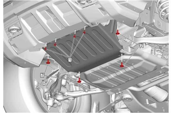
- Front Bumper Fascia Skid Plate Bolt (1) » Remove [4x]
- Underbody Splash Shield Bolt (2) » Remove [4x]
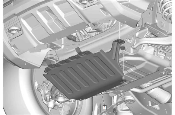
- Underbody Splash Shield (1) » Remove
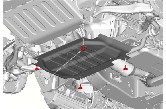
- Underbody Splash Shield Bolt (2) » Remove [2x]
- Underbody Skid Shield (3) » Remove
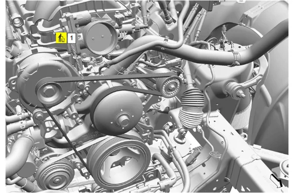
- Using a suitable tool, cut the accessory drive primary belt (1).
- Accessory Drive Primary Belt (1) » Remove and DISCARD
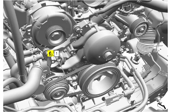
- Using a suitable tool, cut the accessory drive auxiliary belt (1).
- Accessory Drive Auxiliary Belt (1) » Remove and DISCARD
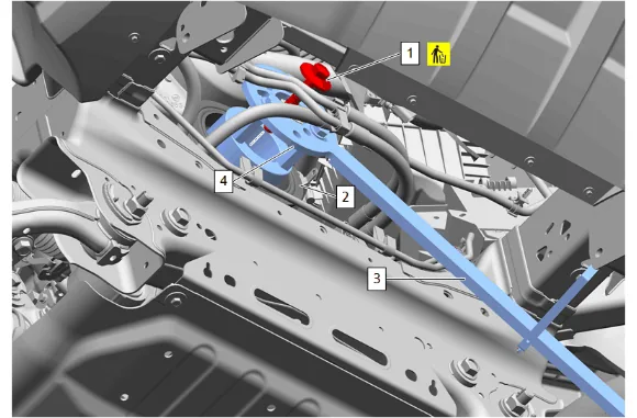
- Install the EN-52287 Balancer Holding Kit (4) and the EN-956-1 Extension Bar (3) to the crankshaft balancer (2).
- Hold the EN-52287 Balancer Holding Kit (4) with the EN-956-1 Extension Bar (3) and remove and DISCARD the crankshaft balancer bolt (1).
- Remove the EN-52287 Balancer Holding Kit (4) and the EN-956-1 Extension Bar (3) from the crankshaft balancer (2).
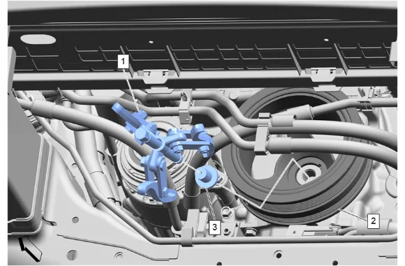
- Install the EN-41816-A Crankshaft Balancer Remover (1) and the EN-44226-5 Crankshaft Protector (3) to the crankshaft balancer (2).
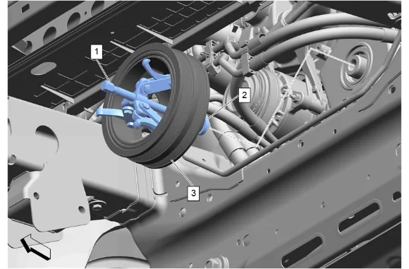
- Using the EN-41816-A Crankshaft Balancer Remover (1) with the EN-44226-5 Crankshaft Protector (2) remove crankshaft balancer (3) from the crankshaft.
- Remove the EN-41816-A Crankshaft Balancer Remover (1) and the EN-44226-5 Crankshaft Protector (2) from the crankshaft balancer (3).
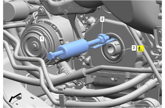
- Install the EN-51096 Seal Remover (2) to the GE-23907-1 Slide Hammer with Shaft (1).
- Slide the large bend of the EN-51096 Seal Remover (2) between the lip of the crankshaft front oil seal and crankshaft. Ensure that the larger bend of the EN-51096 Crankshaft Seal Remover (2) engages the rear side of the crankshaft front oil seal (3).
- Using the EN-51096 Seal Remover (2) and the GE-23907-1 Slide Hammer with Shaft (1) remove the crankshaft front oil seal (3).
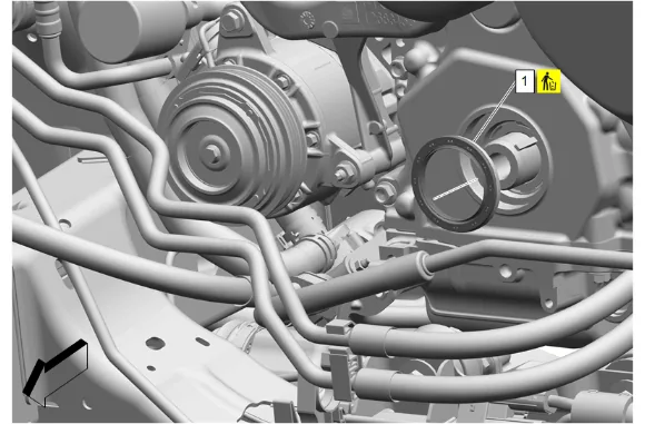
- Crankshaft Front Oil Seal (1) » Remove and DISCARD Cleaning and Inspection Procedure
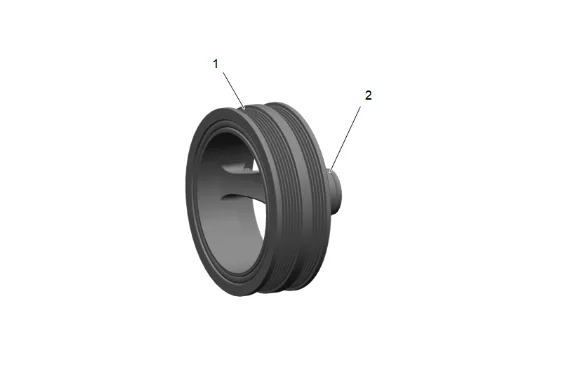
- Clean the crankshaft balancer in solvent.
- Clean the belt grooves of all dirt or debris with a wire brush.
- Dry the crankshaft balancer with compressed air.
- Inspect the crankshaft balancer for the following conditions: Worn, grooved, or damaged hub seal surface A crankshaft balancer hub seal surface (2) with excessive scoring, grooves, rust or other damage must be replaced. Minor imperfections on the hub seal surface (2) may be removed with polishing compound or fine grade emery cloth.
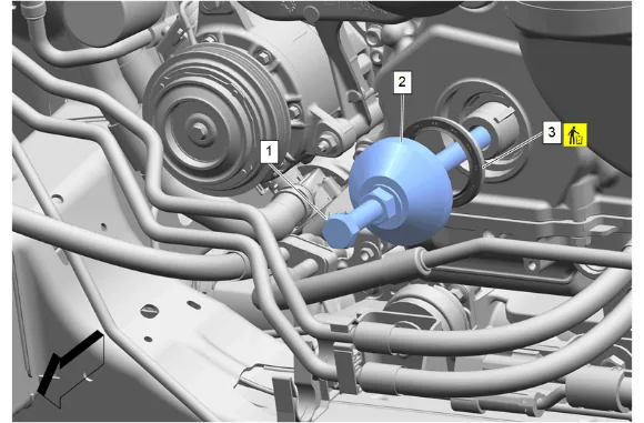
- Install the EN-41478-A Crankshaft Front Oil Seal Installer (1) to the EN-51091 Crankshaft Front Oil Seal Installer (2).
- Install the NEW crankshaft front oil seal (3) with “THIS SIDE OUT” facing away from the engine to the EN-51091 Crankshaft Front Oil Seal Installer (2).
- Install the EN-41478-A Crankshaft Front Oil Seal Installer (1) and the EN-51091 Crankshaft Front Oil Seal Installer (2) into the crankshaft.
- Rotate the EN-51091 Crankshaft Front Oil Seal Installer (2) clockwise until the NEW crankshaft front oil seal (3) enters the engine front cover and seats into the bottom of the engine front cover.
- Remove the EN-41478-A Crankshaft Front Oil Seal Installer (1) and the EN-51091 Crankshaft Front Oil Seal Installer (2) from the crankshaft and engine front cover.
- Inspect the crankshaft front oil seal for proper installation. The crankshaft front oil seal should be installed evenly and completely into the engine front cover.
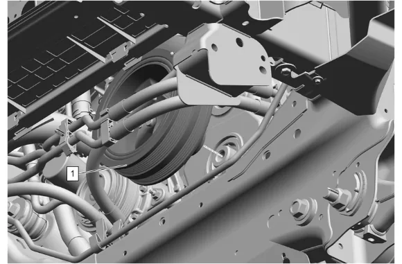
- Crankshaft Balancer (1) » Loosely install
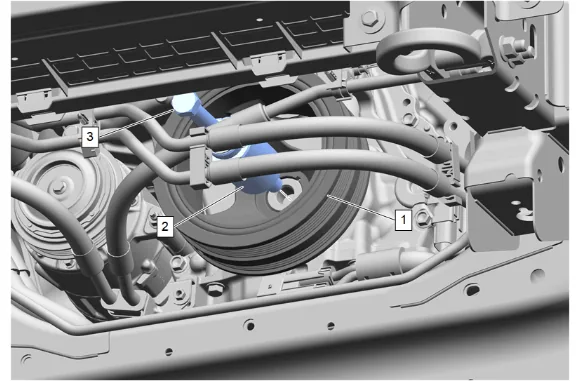
- Install the EN-41478-A Crankshaft Front Oil Seal Installer (3) and the EN-41665-A Crankshaft Balancer and Sprocket Installer (2) to the crankshaft.
- Using the EN-41665-A Crankshaft Balancer and Sprocket Installer (2) properly seat the crankshaft balancer (1).
- Remove the EN-41478-A Crankshaft Front Oil Seal Installer (3) and the EN-41665-A Crankshaft Balancer and Sprocket Installer (2).
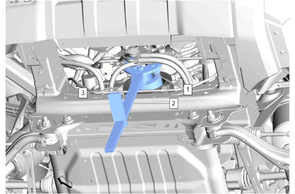
- Install the EN-52287 Balancer Holding Kit (1) and the EN-956-1 Extension Bar (2) to the crankshaft balancer (3).
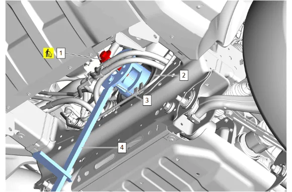
- Crankshaft Balancer Bolt (1) » Install NEW and tighten — Fastener Specifications
- Remove the EN-52287 Balancer Holding Kit (3) and the EN-956-1 Extension Bar (4) from the crankshaft balancer (2).
- Install the accessory drive auxiliary belt following the instructions included with the accessory drive auxiliary belt.
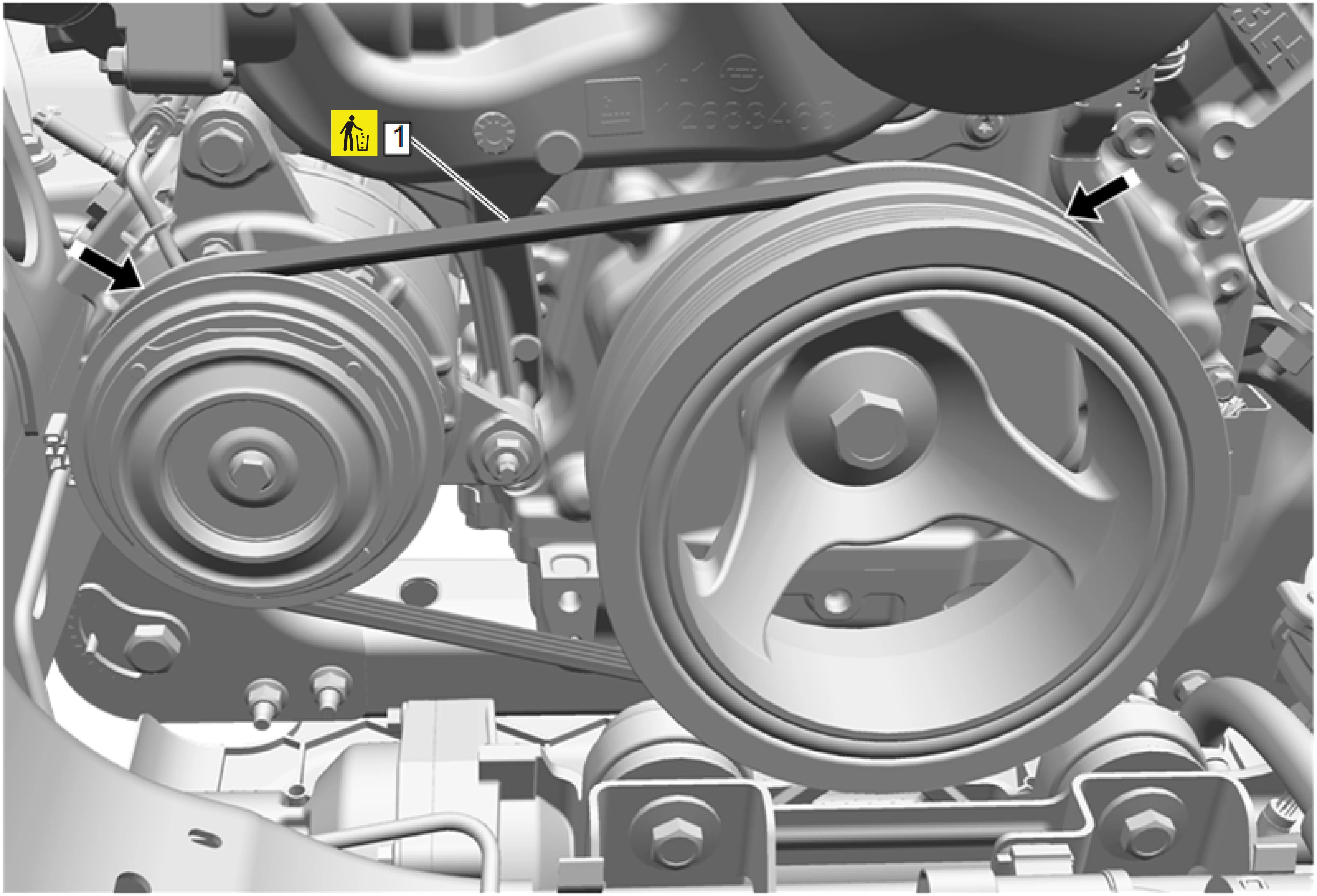
- Inspect the accessory drive auxiliary belt (1) for proper installation and alignment.
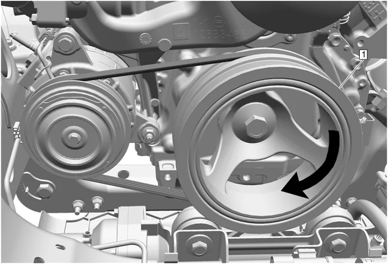
- Rotate the crankshaft balancer (1) an additional 360 degrees to ensure proper accessory drive auxiliary belt installation.
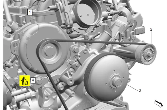
- Position the accessory drive primary belt (4) on the belt idler pulley (2), fan and water pump pulley (3) and generator (1).
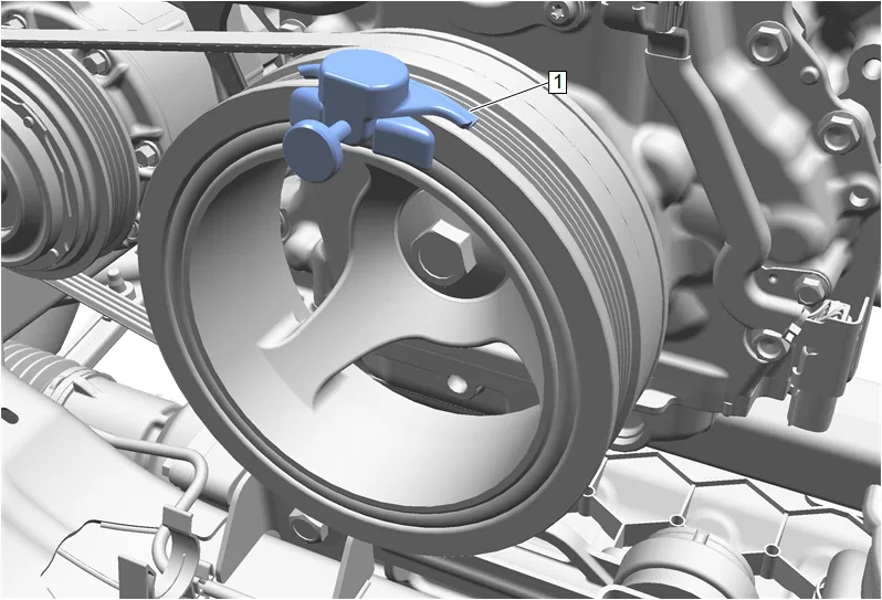
- Install the EN-51767-2 Universal Stretchy Belt Installer (1) onto the crankshaft balancer.
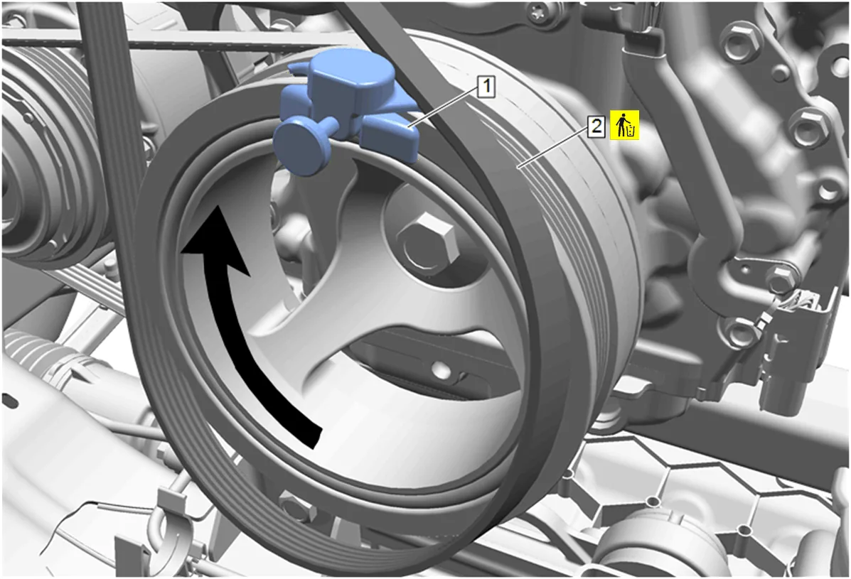
- Position the accessory drive primary belt (2) on the crankshaft balancer.
- Slowly rotate the crankshaft balancer in a clockwise direction until the accessory drive primary belt (2) fully seats on the crankshaft balancer.
- Remove the EN-51767-2 Universal Stretchy Belt Installer (1) from the crankshaft balancer.
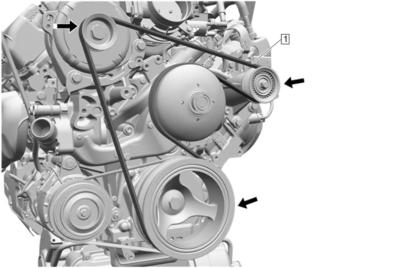
- Inspect the accessory drive primary belt (1) for proper installation and alignment.
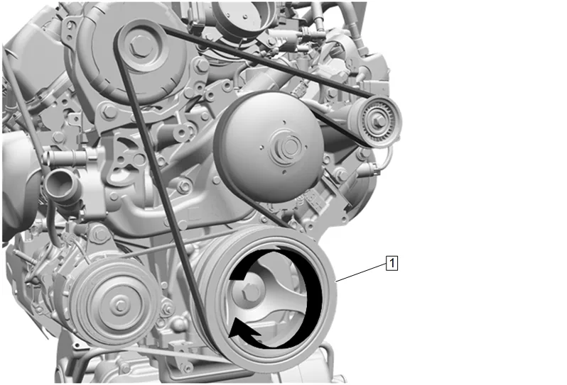
-
Rotate the crankshaft balancer (1) and additional 360 degrees to ensure proper accessory drive primary belt installation.
-
Underbody Skid Shield (3) » Install
-
Underbody Splash Shield Bolt (2) » Install and tighten [2x] — Fastener Specifications
-
Underbody Splash Shield (1) » Install
-
Underbody Splash Shield Bolt (1) » Install and tighten [4x]
-
Underbody Splash Shield Bolt (2) » Install and tighten [4x] — Fastener Specifications
-
Remove the support and lower the vehicle.
-
Connect the battery negative cable. Battery Negative Cable Disconnection and Connection
-
Perform the crankshaft position variation learn procedure. Crankshaft Position Variation Learn