Propeller Shaft Phasing Inspection
Vibration Diagnosis and Correction | Diagnostic Information and Procedures | Document ID: 5044720 Special Tools J-23498-A Driveshaft Inclinometer, or equivalent For equivalent regional tools. Special Tools and Equipment.
- Raise and support the vehicle. On vehicles with solid axles, ensure that the drive axle is supported at ride height– vehicle body supported by suspension components. Ensure the wheels are free to rotate. Lifting and Jacking the Vehicle
- Place the transmission in NEUTRAL.
- Clean any corrosion or foreign material from the universal joint bearing caps.
- Remove any of the universal joint bearing cap snap rings that may interfere with the correct placement of the J-23498-A Driveshaft Inclinometer, or equivalent.
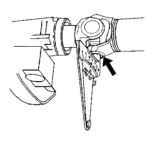
- Inspect the propeller shaft for proper phasing. 5.1. Rotate the propeller shaft or shafts to align the shaft yoke flanges vertically. 5.2. Install the J-23498-A Driveshaft Inclinometer, or equivalent to the lower universal joint bearing cap of the rear universal joint of the shaft. The J-23498-A Driveshaft Inclinometer, or equivalent should be aligned perpendicular to the propeller shaft. 5.3. Set the indicator line on the J-23498-A Driveshaft Inclinometer, or equivalent to 15, the horizontal reference. 5.4. Rotate the propeller shaft slightly to center the bubble to the indicator. The universal joint is now vertical. 5.5. Without disturbing the setting on the J-23498-A Driveshaft Inclinometer, or equivalent, remove the J-23498-A Driveshaft Inclinometer, or equivalent from the rear universal joint bearing cap. 5.6. Install the J-23498-A Driveshaft Inclinometer, or equivalent to the lower universal joint bearing cap of the front universal joint of the same shaft. 5.7. Observe and record the reading of the front universal joint with the J-23498-A Driveshaft Inclinometer, or equivalent still set to 15, the horizontal reference. 6. For propeller systems with 3 universal joints, rotate the shafts 1/4 turn and repeat steps 5.1–5.7 for the other propeller shaft.
- If the difference between the front and rear universal joints of a welded yoke propeller shaft is 3 degrees or less, the propeller shaft is properly phased.
- If the difference between the front and rear universal joints of a welded-yoke propeller shaft is greater than 3 degrees, the propeller shaft is either constructed improperly, or damaged from twisting. Propeller Shaft Phasing Correction
- If the difference between the welded yoke and slip yoke of a propeller shaft is 1.5 degrees or less, the propeller shaft is properly phased.
- If the difference between the welded yoke and slip yoke of a propeller shaft is greater than 1.5 degrees, the propeller shaft is either constructed improperly, or damaged from twisting. Propeller Shaft Phasing Correction