Pinion Depth Adjustment (G86 9.76 Inch Axle)
Special Tools DT-21777-B Pinion Setting Gauge and Components DT-51173 Pinion Shim Selection Adapter Kit DT-52901 Main Bearing Cap Bridge Assembly Equivalent regional tools: Special Tools Procedure
- Using the proper axle lubricant, lubricant the differential pinion bearings. Adhesives, Fluids, Lubricants, and Sealers
- Install the differential pinion bearings into the axle housing.
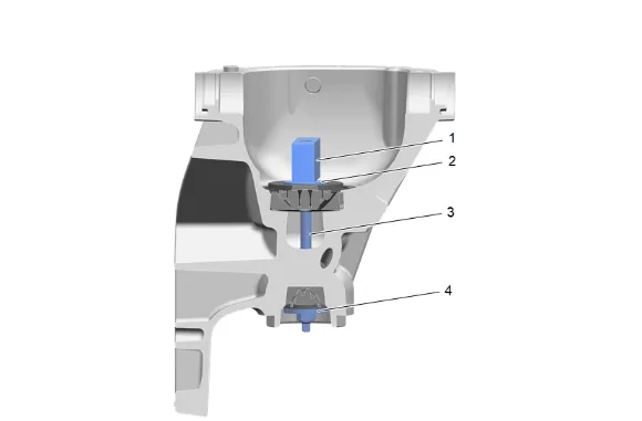
- Install the DT-51173-3 Rear Bearing Pilot (2), DT-21777-43 Stud Assembly Bolt (3), DT- 51173-2 Front Bearing Pilot (4), and the DT-51173-1 Gauge Block (1).
- Using an inch pound torque wrench and the DT-21777-43 Stud Assembly Bolt (3), tighten the nut until the specified rotating torque for the pinion bearings is obtained, refer to Axle Preload and Backlash Specifications.
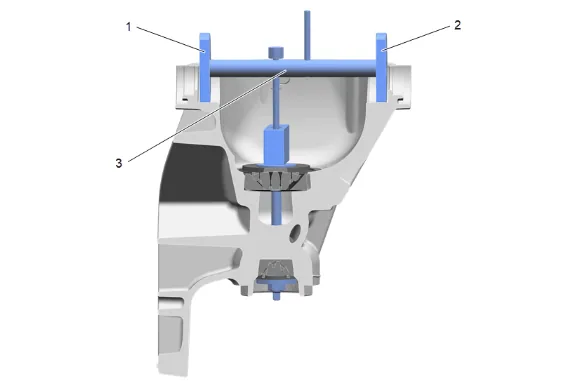
- Install the DT-21777-1 Arbor Assembly (3) with the DT-21777-86 Side Bearing Discs (1) and (2) into the differential carrier bores.
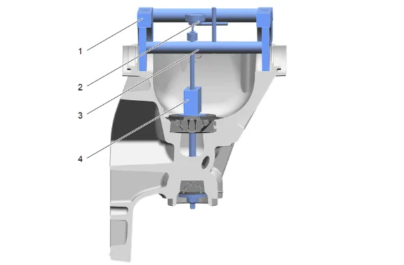
- Install the DT-52901 Main Bearing Cap Bridge Assembly (1).
- Install and tighten the 4 rear axle housing cover bolts to hold DT-52901 Main Bearing Cap Bridge Assembly. Fastener Specifications
- Rotate the DT-21777-1 Arbor Assembly (3) within the DT-21777-86 Side Bearing Discs (1) and (2). The DT-21777-1 Arbor Assembly (3) must rotate back and forth freely within the discs. If the DT-21777-1 Arbor Assembly (3) does not rotate freely, disassemble the components, inspect for proper seating and/or mis-aligned components and re-assemble.
- Adjust the arbor of the DT-21777-1 Arbor Assembly (3) to touch the top of the DT-51173-1 Gauge Block (4).
- Install the J-8001 Dial Indicator Set (2) to the DT-21777-1 Arbor Assembly (3) as follows: 10.1. Loosely clamp the J-8001 Dial Indicator Set onto the stem on the DT-21777-1 Arbor Assembly. 10.2. Place the contact pad of the J-8001 Dial Indicator Set onto the mounting post of the DT- 21777-1 Arbor Assembly. 10.3. With the contact pad of the J-8001 Dial Indicator Set touching the mounting post of the DT-21777-1 Arbor Assembly, loosen the lock nut on the J-8001 Dial Indicator Set and push down on the J–8001 Dial Indicator Set until the needle of the J-8001 Dial Indicator Set has turned approximately 3/4 of a turn clockwise. 10.4. Tighten the clamp on the J-8001 Dial Indicator Set indicator finger tight.
- Rotate the DT-21777-1 Arbor Assembly (3) back and forth until the needle of the J-8001 Dial Indicator Set indicates the greatest deflection.
- At the greatest point of deflection, adjust the housing of the J-8001 Dial Indicator Set as necessary to set the needle to zero.
- Rotate the plunger of the DT-21777-1 Arbor Assembly (3) away from the DT-51173-1 Gauge Block (4).
- The value indicated on the J-8001 Dial Indicator Set, when the DT-21777-1 Arbor Assembly (3) is rotated away from the DT-51173-1 Gauge Block (4), is the thickness of the shim needed in order to set the depth of the pinion. Record the measurement.
- Select the shim that indicates the proper thickness. Measure the shim with a micrometer in order to verify that the thickness is correct.
- Remove the pinion depth setting tools.
- Remove the pinion bearings.
- Return to the previous procedure and continue from appropriate step which linked to this procedure.