New Product Information
The purpose of New Product Information is to document, important product changes which occur either model year-to-model year or interim model year. Changes may include one or more of the following items: Specification Changes New sealants and/or adhesives Disassembly and assembly procedure revisions Mechanical and diagnostic procedure revisions New special tools required Interim model year design changes A component comparison from the previous model year 2019 NQH/NPO- Model Year Design Change Beginning in 2019 model year for NQH / NPO transfer case will be available. Changes include, but not limited to: Front output shaft now is an external spline Front output NEW seal design and slinger implementation Front output shaft boot and clamps. Speed sensor has been removed, reluctor wheel removed and replaced with a spacer Actuator electronics
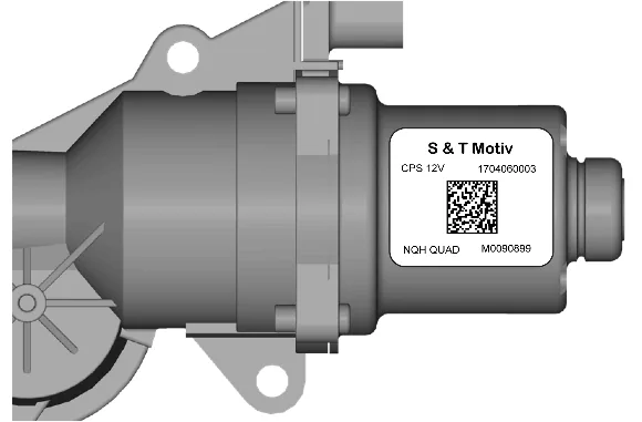
IPS is used as a high-resolution sensor to measure motor speed and direction. Sensor outputs are two PWM signals 0–5 volts at constant duty cycle. As the motor speed changes, the frequency of the PWM signal will change. Motor direction change is measured by the phase shift between Incremental Sensor Output B and Incremental Sensor Output A. New 19MY actuator can be identified with label in component. Look for “NQH QUAD” in bottom left corner. If a part number from a previous model year is installed by mistake, the system will not set a DTC until movement is requested. Once there is actuator movement, the TCCM will set run time correlation fault (C15A9 $5A). New collector magnet RPS gasket
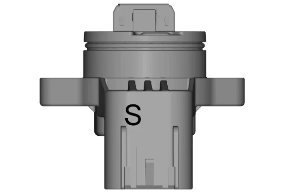
New 19MY RPS (position sensor) can be identified with a “S” mark in following location (RPS connector). If a part number from a previous model year is installed by mistake, the system will not set a DTC until movement is requested in the high torque range. In this range, there will be a large enough difference between the RPS and the IPS. The TCCM will then set run time correlation fault (C15A9 $5A).
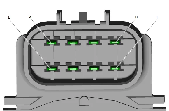
Actuator Pinout Connector
| PIN | ACTUATOR PIN OUT |
|---|---|
| A | MOTOR POWER INPUT (-V) |
| B | LOCK/BRAKE POWER INPUT (+V) |
| C | LOCK/BRAKE POWER INPUT (-V) |
| D | MOTOR POWER INPUT (+V) |
| E | INCREMENTAL SENSOR OUTPUT B |
| F | INCREMENTAL SENSOR OUTPUT A |
| G | SENSOR POWER INPUT (+V) |
| H | SENSOR POWER INPUT (-V) |
Shifting to Transfer Case neutral. Transfer Case NEUTRAL position may be obtained only if the following criteria have been met: Start the vehicle or turn the ignition on. Shift the transmission to NEUTRAL. Shift the transfer case to 2 HI. (Shifts to transfer case neutral are only allowed when transfer case initial state is 2 HI.) Apply park brake and/or Service brake. If Park Brake and/or service brake is not applied within 20 seconds, transfer case will remain in original state. Shifting to 2WD with transmission in Park (P) During this shift, EPB (Electric Parking Brake) will engage. This is normal operation, behavior is described in Owner’s Manual. 2017 NQF/NQG- Interim Model Year Design Change – DT–51204 - New Design Case Separating Tool
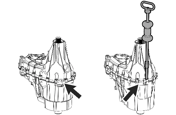
For 2017MY super heavy duty NQF / NQG transfer cases with diesel engine and Alison transmission, one pair of the transfer case case-half separating flanges have been removed to address in-vehicle packaging concerns. With the removal of the case separating flanges, a new design tool has been developed. DT–51204 Case Separating Tool has been created to assist the technician when performing disassembly of the transfer case. The new design tool is to be used in conjunction with GE-02619-A Slide Hammer when separating the case halve. 2016 NQF / NQG with MW7 Transmission Interim Model Year Design Change - Front Case Half - Addition of Transmission Extension Housing Seal and New Design Gasket
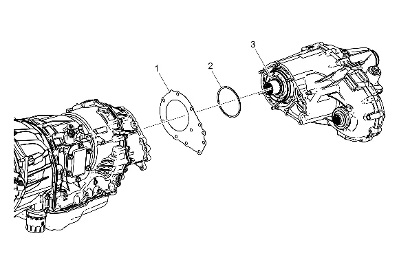
Interim 2016 MY,a new design seal (2) has been added to the rear of transmission extension housing and front of transfer case interface. A new design gasket (1) is to be used in conjunction with the new seal. The purpose of the seal is to control and limit the amount of transmission fluid that enters the wet-cavity area. Earlier applications do not have the seal. When servicing an older application that does not have the seal, it is recommended to install the new seal and new design gasket prior to reassembly. The new gasket is required when using the new seal. When installed, the seal should be fully seated against front of the Transfer case (3). 2015 NQF/NQG- Interim Model Year Design Change (RPO-AVF) – Digital Speed Sensor
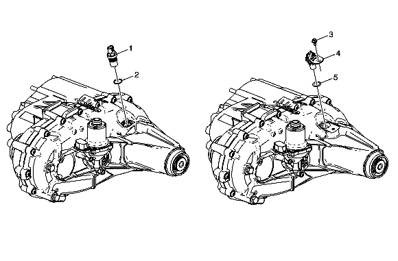
- Vehicle Speed Sensor - Non-Digital Assembly
- Vehicle Speed Sensor - Non-Digital Assembly Seal (O-ring)
- Vehicle Speed Sensor - Digital Assembly Bolt
- Vehicle Speed Sensor - Digital Assembly
- Vehicle Speed Sensor - Digital Assembly Seal (O-ring) The RPO-AVF designation was used interim 2015 MY to provide a break-point for a variety of changes that occurred for K-truck applications. The transfer case digital speed sensor change is just one of many within the RPO-AVF designation. Refer to applicable service bulletins for additional information. Interim 2015 model year for Magna HD NQF and NQG transfer case applications with Duramax engine and Allison transmission (RPO-MW7), a NEW design digital speed sensor (4) is to be implemented. Non-AVF applications will continue to use the threaded-into-the-rear case design speed sensor (1). Applications with RPO AVF will include a non-threaded push-into-the-bore design speed sensor (4) that is retained by a bolt (3). To differentiate between digital speed sensor (4) and non-digital speed sensor (1) applications, the RPO AVF is used to identify digital sensor applications. 2015 NQH-HD Model Year Design Change – Addition of a NQH Transfer Case with HD Internal Components
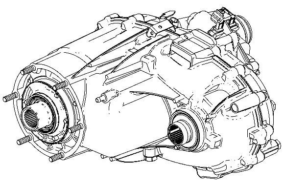
Beginning in 2015 model year for 3500 series SUV only, a HD version of the NQH transfer case will be available. Changes include, but not limited to: Six pinion planetary carrier HD drive chain and sprockets HD rear output shaft 2014 NQH/NQG-LD Model Year Design Change – Addition of a Tuned Vibration Adapter (dampener) for V-6 Engine RPO LV3 Applications
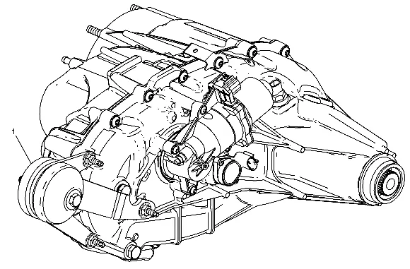
Beginning in 2014 model year for V-6 engine RPO LV3 applications, a dampener (1) has been added to the exterior of the NQH and NQG-LD transfer cases. 2013 Input Shaft Seal Installer Revisions
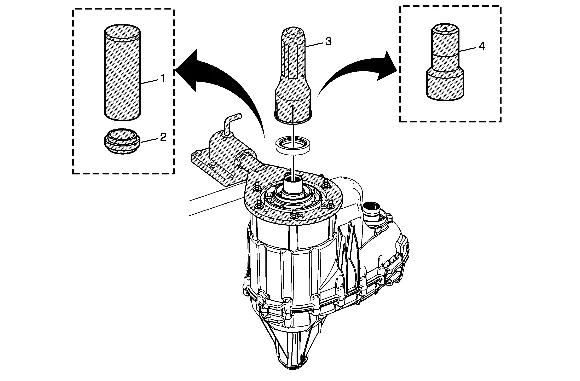
Beginning July 2013, a NEW input shaft seal installer has been identified for Magna transfer case applications (all model years and all RPOs). The new seal installer is identified as DT-50648-A Seal Installer (4). The DT-50648-A Seal Installer is to be used in place of J-42738 Seal Installer (3), as well as J-36183 Press Tube (1) and J-36184 Press Tube Reducer (2). J-42738 Seal Installer is to be discontinued and no longer available. 2012 Interim Model Year Design Change – NQF/NQG/NQH Front Case Half Assembly, Input Shaft, Planetary Carrier High/Low Clutch Interim 2012 model year for Magna light-duty and heavy-duty transfer case RPOs NQF / NQG / NQH, a second-design front case half assembly, planetary internal gear, gear retaining ring, locking plate, thrust washer-front, input shaft, pilot bearing, thrust washer-rear, high/low planetary carrier, and high/low clutch were implemented into second-design assemblies. The second-design light duty (LD), heavy duty (HD), and super-heavy duty (SHD) applications have a reduced OD dimension carrier and the second-design planetary internal gear has a reduced ID dimension. The planetary internal gear is a press-fit non-serviceable component and must be serviced with the front case half assembly. In service it is possible that a new or remanufactured transfer case may contain first or second-design content. If a second-design transfer case has been installed into a vehicle that originally contained a first- design assembly, TCCM reprogramming is not required. Assembly and Component Identification
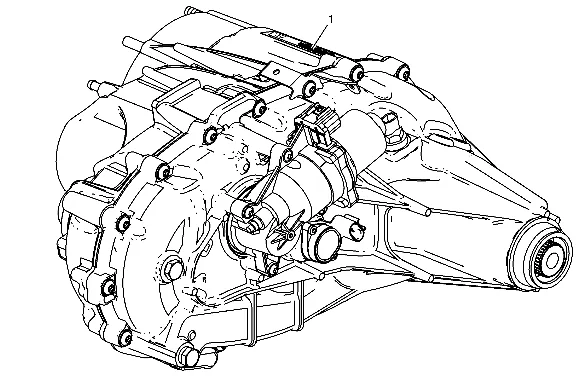
- Check the transfer case assembly bar code label (1) to determine if the assembly contains first or second design components. Refer to: Magna Transfer Case Bar Code Label and the Production Assembly Breakpoints Table.
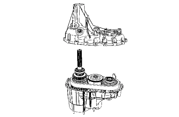
- Separate the case halves. Refer to: Transfer Case Disassemble.
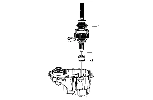
- Remove the rear output shaft assembly (1) and the high/low clutch (2).
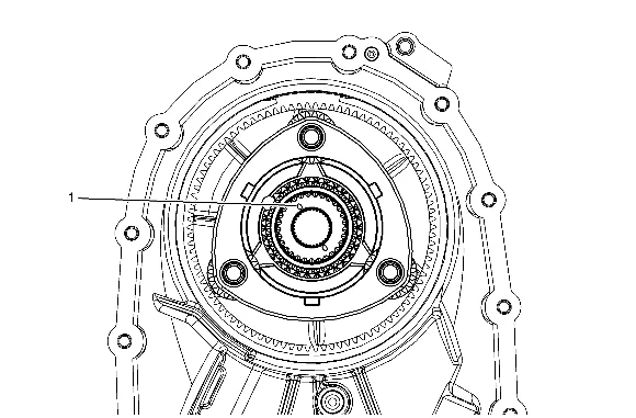
- Inspect the rear face of the input shaft. (LD) A light duty assembly with first design components can be identified by an input shaft with 2 oil drain holes (1) 180 degrees apart. A light duty assembly with second design components can be identified by an input shaft with 3 oil drain holes 120 degrees apart.
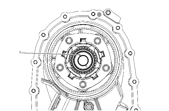
- Inspect the rear face of the input shaft. (HD) A heavy duty assembly with first design components can be identified by an input shaft with 2 oil drain holes (1) 180 degrees apart. A heavy duty assembly with second design components can be identified by an input shaft with 3 oil drain holes 120 degrees apart.
- Refer to: Appropriate Parts Identification Table. Magna Transfer Case Bar Code Label The design level and component content of the transfer case can be determined by referencing the assembly part number located on the identification label.
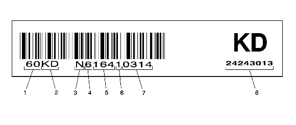
- Component Identifier
- GM Broadcast Code
- Supplier Code
- Production Year
- Julian Date of the Year
- Assembly Line Number
- Sequential Number
- GM Assembly Part Number Production Assembly Breakpoints
| First Design Assembly PN | Second Design Assembly PN | RPO | Approximate Production Breakpoint | Vehicle/Transmi RPO |
|---|---|---|---|---|
| 24256476 | 24261560 | NP0 | March 2012 | K100 / MYC |
| 24256475 | 24261517 | NQH | January 2012 | K200 / MYD |
| 24256474 | 24261516 | NQH | January 2012 | K100 / M99 |
| 24256473 | 24261515 | NQH | January 2011 | K100 / M30 |
| 24256472 | 24261514 | NQH | December 2011 | K100 / MYC |
| 24257578 | 24261513 | NQF | December 2011 | K200 / MYD |
| 24257577 | 24261512 | NQF | January 2012 | K200 / 300 / MW7 |
| 24257576 | 24261511 | NQF | December 2011 | K200 / 300 / MYD |
| 24257581 | 24261510 | NQG | January 2011 | K200 / MYD / +Z49 |
| 24257580 | 24261509 | NQG | January 2012 | K200 / 300 / MW7 |
| 24257579 | 24261508 | NQG | December 2011 | K200 / 300 / MYD / -Z49 |
| 24252685 | 24261507 | NQG | December 2011 | K100 / M30 |
| 24252684 | 24261506 | NQG | January 2011 | K100 / MYC |
Magna Light Duty NQG/NQH/NP0 – First Design
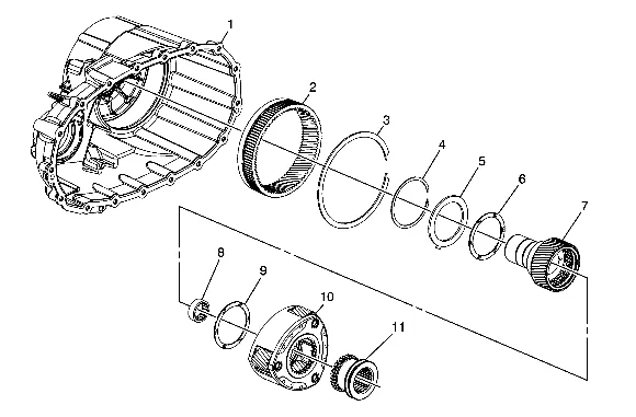
| Magna Light Duty NQG/NQH/NP0 – First Design | |||||
|---|---|---|---|---|---|
| Callout | Description | GM PN | Service Usage | ||
| 1 | Front Case Half Assembly - w/gear (2) and ring 3) | 19132998 | NQH | ||
| 1 | Front Case Half Assembly - w/gear (2) and ring (3) | 19133000 | NQG | ||
| 1 | Front Case Half Assembly - w/o gear (2) and ring (3) | 19255999 | NP0 | ||
| 2 | High/Low Internal Gear-Not serviceable- part of case assembly | NO/PN | NQG/NQH | ||
| 3 | High/Low Internal Gear Retaining Ring | 19133009 | NQG/NQH | ||
| 4 | High/Low Planetary Carrier Retaining Ring | 19132997 | NQG/NQH | ||
| 5 | High/Low Locking Plate-Single tab design | 19132996 | NQG/NQH | ||
| 6 | Thrust Washer-Front- | 19132995 | NQG/NQH |
| Magna Light Duty NQG/NQH/NP0 – First Design | |||
|---|---|---|---|
| Callout | Description | GM PN | Service Usage |
| No tab design | |||
| 7 | Input Shaft Assembly - w/pilot bearing | 19132977 | NQG/NQH-w/M30 |
| 7 | Input Shaft Assembly- w/pilot bearing | 19132978 | NQH-w/M99 |
| NQG/ NQH-w/MYC | |||
| 7 | Input Shaft Assembly- w/pilot bearing | 19255997 | NP0-w/MYC |
| 8 | Pilot Bearing | 19132983 | NQG/NQH/NP0 |
| 9 | Thrust Washer-Rear- No tab design | 19132995 | NQG/NQH |
| 10 | High/Low Planetary Carrier Assembly- Three pinion design | 19132986 | NQG/NQH |
| 11 | High/Low Clutch | 19260068 | NQG/NQH - w/M30 |
| 11 | High/Low Clutch | 19260067 | NQG/NQH w/MYC and NQH w/M99 |
Magna Light Duty NQG/NQH/NP0 – Second Design
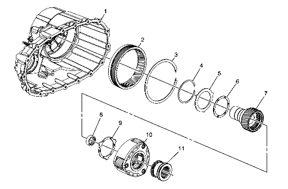
| Magna Light Duty NQG/NQH/NP0 – Second Design | |||||
|---|---|---|---|---|---|
| Callout | Description | GM PN | Service Usage | ||
| 1 | Front Case Half Assembly - w/gear (2) and ring (3) | 19299077 | NQH | ||
| 1 | Front Case Half Assembly - w/gear (2) and ring (3) | 19299078 | NQG | ||
| 1 | Front Case Half Assembly – w/o gear (2) and ring (3) | 19299076 | NP0 Note: The second design NP0 front case half assembly is interchangeable with first design | ||
| 2 | High/Low Internal Gear-Not serviceable- part of case assembly | NO/PN | NQG/NQH | ||
| 3 | High/Low Internal Gear Retaining Ring | 14037953 | NQG/NQH | ||
| 4 | High/Low Planetary Carrier Retaining Ring | 15547397 | NQG/NQH | ||
| 5 | High/Low Locking Plate- three tab design | 19300745 | NQG/NQH | ||
| 6 | Thrust Washer-Front - No tab design | 12470959 | NQG/NQH | ||
| 7 | Input Shaft Assembly- w/pilot bearing | 19299085 | NQG/NQH-w/M30 | ||
| 7 | Input Shaft Assembly - w/pilot bearing | 19299088 | NQH-w/M99 | ||
| NQG/NQH-w/MYC | |||||
| 7 | Input Shaft Assembly- w/pilot bearing | 19255997 | NP0-w/MYC | ||
| 8 | Pilot Bearing | 19132983 | NQG/NQH/NP0 | ||
| 9 | Thrust Washer-Rear- Three tab design | 19300746 | NQG/NQH | ||
| 10 | High/Low Planetary | 19299090 | NQG/NQH |
| Magna Light Duty NQG/NQH/NP0 – Second Design | |||
|---|---|---|---|
| Callout | Description | GM PN | Service Usage |
| Three pinion design | |||
| 11 | High/Low Clutch | 19299092 | NQG/NQH - w/M30 |
| 11 | High/Low Clutch | 19299093 | NQG/NQH w/MYC and NQH w/M99 |
Magna Heavy Duty NQF/NQG/NQH – First Design
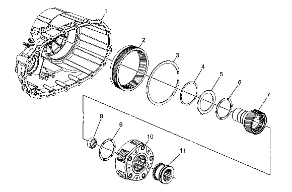
| Magna Heavy Duty NQF/NQG/NQH – First Design | |||||
|---|---|---|---|---|---|
| Callout | Description | GM PN | Service Usage | ||
| 1 | Front Case Half Assembly w/gear (2) and ring (3) | 19257420 | 2011-13 NQF | ||
| 1 | Front Case Half Assembly w/gear (2) and ring (3) | 19133000 | 2007-10 NQG | ||
| 1 | Front Case Half Assembly w/gear (2) | 19259038 | 2011-13 NQG | ||
| © 202a3n Gd erninegr a(3l )Motors. | All rights reserved. |
| Magna Heavy Duty NQF/NQG/NQH – First Design | |||
|---|---|---|---|
| Callout | Description | GM PN | Service Usage |
| 1 | Front Case Half Assembly w/gear (2) and ring (3) | 19132998 | 2007-13 NQH |
| 2 | High/Low Internal Gear-Not serviceable- part of case assembly | NO/PN | NQF/NQG/NQH |
| 3 | High/Low Internal Gear Retaining Ring | 19133009 | NQF/NQG/NQH |
| 4 | High/Low Planetary Carrier Retaining Ring | 19132997 | NQF/NQG/NQH |
| 5 | High/Low Locking Plate-Single tab design | 19132996 | NQF/NQG/NQH |
| 6 | Thrust Washer-No tab design - Front | 19132995 | NQF/NQGF/NQH |
| 7 | Input Shaft Assembly w/pilot bearing | 19132979 | NQH w/MYD |
| 07-10MY NQF/NQG w/MYD and MW7 | |||
| 7 | Input Shaft Assembly- w/pilot bearing | 19257419 | 2007-13 NQF/NQG w/MYD |
| 7 | Input Shaft Assembly- w/pilot bearing | 19259039 | 2011-13 NQF/NQG w/MW7 |
| 8 | Pilot Bearing | 19259040 | 2011-13MY NQF/NQG w/MW7 |
| 8 | Pilot Bearing | 19132984 | 2007-10MY NQF/NQG/NQH - w/ MW7 / MYD |
| 2007-13 NQH w/MYD | |||
| 2011-13 NQF/NQG w/ MYD | |||
| 9 | Thrust Washer-No tab design-Rear | 19132995 | NQG/NQH |
| 2011-13 NQF |
| Magna Heavy Duty NQF/NQG/NQH – First Design | |||
|---|---|---|---|
| Callout | Description | GM PN | Service Usage |
| 10 | High/Low Planetary Carrier Assembly-Five pinion design | 19132987 | NQG/NQH |
| 2011-13 NQF | |||
| 11 | High/Low Clutch | 19260067 | NQG/NQH |
| 2011-13 NQF |
Magna Heavy Duty NQF/NQG/NQH – Second Design
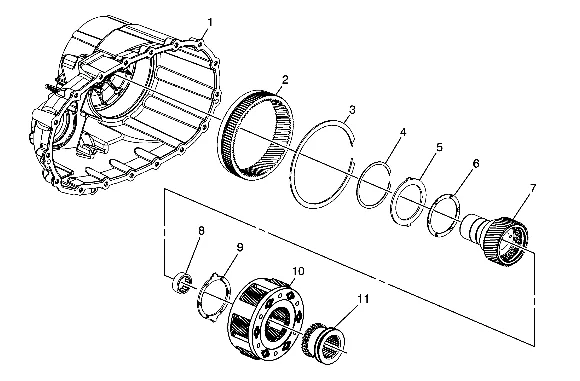
| Magna Heavy Duty NQF/NQG/NQH – Second Design | |||
|---|---|---|---|
| Callout | Description | GM PN | Service Usage |
| 1 | Front Case Half Assembly w/gear (2) and ring (3) | 19299079 | 2011-13 NQF |
| 1 | Front Case Half Assembly w/gear (2) and ring (3) | 19299078 | 2007-10 NQG |
| 1 | Front Case Half Assembly w/gear (2) and ring (3) | 19299080 | 2011-13 NQG |
| Magna Heavy Duty NQF/NQG/NQH – Second Design | |||
|---|---|---|---|
| Callout | Description | GM PN | Service Usage |
| 1 | Front Case Half Assembly w/gear (2) and ring (3) | 19299077 | 2007-13 NQH |
| 2 | High/Low Internal Gear-Not serviceable- part of case assembly | NO/PN | NQF/NQG/NQH |
| 3 | High/Low Internal Gear Retaining Ring | 14037953 | NQF/NQG/NQH |
| 4 | High/Low Planetary Carrier Retaining Ring | 15547397 | NQF/NQG/NQH |
| 5 | High/Low Locking Plate-Two tab design | 15664905 | NQF/NQG/NQH |
| 6 | Thrust Washer-No tab design - Front | 12470959 | NQF/NQGF/NQH |
| 7 | Input Shaft Assembly- w/pilot bearing | 19299086 | NQH w/MYD |
| 07-10MY NQG w/MYD and MW7 | |||
| 7 | Input Shaft Assembly- w/pilot bearing | 19299087 | 2011-13 NQF/NQG w/MYD |
| 7 | Input Shaft Assembly- w/pilot bearing | 19299089 | 2011-13 NQF/NQG w/MW7 |
| 8 | Pilot Bearing | 19259040 | 2011-13MY NQF/NQG w/MW7 |
| 8 | Pilot Bearing | 19132984 | 2007-10MY NQF/NQG/NQH - w/ MW7 / MYD |
| 2007-13 NQH w/MYD | |||
| 2011-13 NQF/NQG w/ MYD | |||
| 9 | Thrust Washer-Two tab design-Rear | 15547390 | NQG/NQH |
| 2011-13 NQF |
| Magna Heavy Duty NQF/NQG/NQH – Second Design | |||
|---|---|---|---|
| Callout | Description | GM PN | Service Usage |
| 10 | High/Low Planetary Carrier Assembly-Six pinion design | 19299091 | NQG/NQH |
| 2011-13 NQF | |||
| 11 | High/Low Clutch | 19299093 | NQG/NQH |
| 2011-13 NQF |
Front Case Half Identification
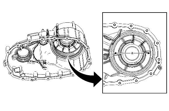
The first design front case half assembly can be identified as having an internal gear that is a 94 tooth design with an inside diameter (a) of 148.5 mm (5.85 in). The second design front case half assembly can be identified as having an internal gear that is a 91 tooth design with an inside diameter (a) of 142 mm (5.59 in). Input Shaft Identification
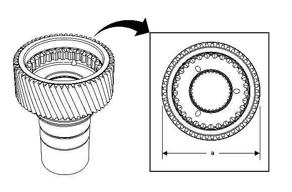
The first design input shaft can be identified as a 56 tooth design with an outside diameter (a) of91.4 mm (3.60 in) and two oil drain holes 180 degrees apart. The second design input shaft can be identified as a 53 tooth design with an outside diameter (a) of87.50 mm (3.44 in) and three oil drain holes120 degrees apart. High/Low Planetary Carrier Assembly Identification
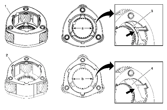
The first-design light-duty 3-pinion high/low planetary carrier (1) can be identified as having a 30 tooth design with an inside diameter (a) of 61.3 mm (2.41 in). In addition, the first-design carrier can also be identified by the presence of a recessed washer pocket (3) at the rear thrust washer location. The second-design light-duty 3-pinion high/low planetary carrier (2) can be identified as having a 29 tooth design with an inside diameter (b) of 60.2 mm (2.37 in). In addition, the second-design carrier can also be identified by the lack of a recessed washer pocket (4) at the rear thrust washer location.
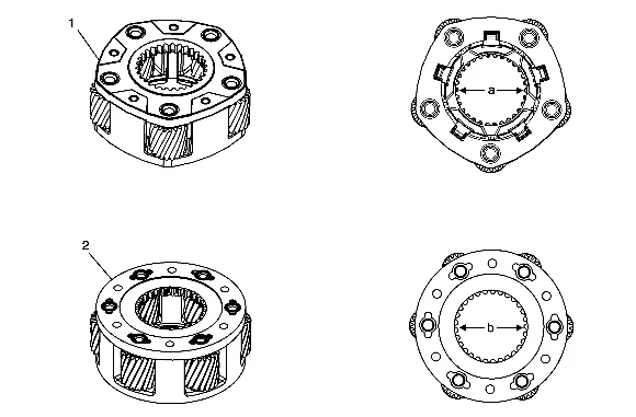
The first-design heavy-duty 5-pinion high/low planetary carrier (1) can be identified as having 5 pinions and a 30 tooth design with an inside diameter (a) of 61.3 mm (2.41 in). The second-design heavy-duty 6-pinion high/low planetary carrier (2) can be identified as having 6 pinions and a 29 tooth design with an inside diameter (b) of 60.2 mm (2.37 in). High/Low Clutch
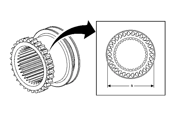
The first design high/low clutch can be identified as having a 30 tooth design with a gear tooth outside diameter (a) of 65.50 mm (2.58 in). The second design high/low clutch can be identified as having a 29 tooth design with a gear tooth outside diameter (a) of 63.25 mm (2.49 in). Component Replacement – Light Duty Conversion from First Design to Second Design
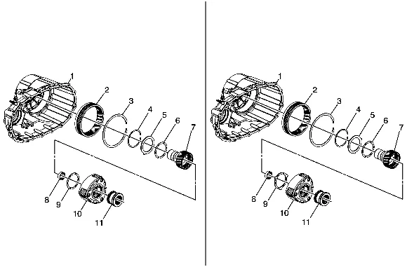
It is possible to repair a first-design assembly using second-design components. Refer to the parts catalog and the Parts Identification Tables above for component part number clarification. When servicing a first-design LD assembly with LD second-design components, the following components MUST be replaced as a group:
- Front Case Half Assembly – with internal gear and retaining ring
- Locking Plate
- Thrust Washer (front)
- Input Shaft
- Pilot Bearing
- Thrust Washer (rear)
- Planetary Carrier Assembly
- High/Low Clutch
- Thrust Washer
- High/Low Planetary Carrier Assembly
- High/Low Clutch Component Replacement – Heavy Duty Conversion from First Design to Second Design
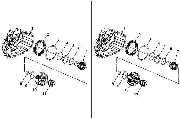
It is possible to repair a first-design HD assembly using second-design HD components. Refer to the parts catalog and the Parts Identification Tables above for component part number clarification. When servicing a first-design HD assembly with HD second-design components, the following components MUST be replaced as a group:
- Front Case Half Assembly – with internal gear and retaining ring
- Locking Plate
- Thrust Washer (front)
- Input Shaft
- Pilot Bearing
- Thrust Washer (rear)
- Planetary Carrier Assembly
- High/Low Clutch
- Thrust Washer
- High/Low Planetary Carrier Assembly
- High/Low Clutch Production Changes Summary For production the following transfer cases variations were produced: 2007-12i Magna LD NQG/NQH – produced with first-design content. First design service components are available. A second-design assembly may be used for back-service in a first- design application. 2007-10 Magna HD NQF – produced with only first-design content. Service components are available. 2007-10 Magna HD NQG – produced with only first-design content. Service assemblies may contain either first or second design content. Both first and second design service components are available. 2007-12i Magna HD NQH – produced with first-design content. First design service components are available. A second-design assembly may be used for back-service in a first-design application. 2011-12i Magna SHD NQF/NQG – produced with first design content. First design service components are available. A second-design assembly may be used for back-service in a first- design application. 2012i-13 Magna LD NQG/NQH – produced with second-design content. Second design service components are available. 2012i-13 Magna HD NQH – produced with second-design content. Second design service components are available 2012i-13 Magna SHD NQF/NQG – produced with second-design content. Second design service components are available 2012 Interim Model Year Design Change – NQG High/Low Shift Fork, Fork Pad, and High/Low Clutch
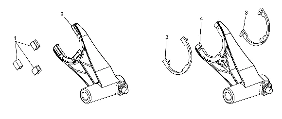
Interim 2012 model year the High/Low shift fork, fork pad, and High/Low clutch design changed. The first design forks (2) can be identified as having three flat un-notched fork pad areas with three separate fork pads (1). The second design forks (4) can be identified as having a half-round shaped pad area with three notches for pad orientation and installation and upper and lower half-round fork pads (3). The second design shift fork (4) and pads (3) are the only design available for service and must be used with the second design High/Low clutch.
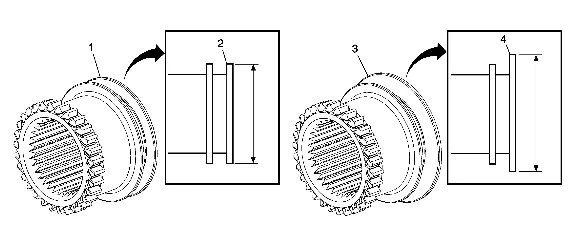
Interim 2012 model year the High/Low shift fork, fork pad, and High/Low clutch design changed. The first design high/low clutch (1) can be identified by having a 73 mm (2.87 in) OD rear flange (2). The second design high/low clutch (3) can be identified by having a76 mm (2.99 in) OD rear flange (4). For service: The first design 73 mm (2.87in) high/low clutch may NOT be used with the second design fork and pad. The second design 76 mm (2.99in) high/low clutch must be used with the second design fork and fork pad. The second design 76 mm (2.99in) high/low clutch may also be used with the first design fork and pad if first design fork replacement is not required. 2011 Interim Model Year Design Change – NQF/NQG HD and SHD Design Change - Main shaft, pin, and thrust washer
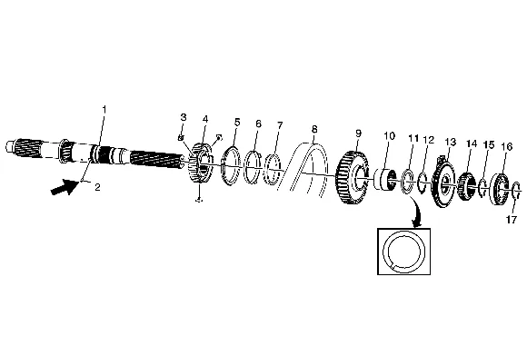
Beginning in 2011 model year for NQF / NQG HD and SHD applications, an anti-rotation main-shaft pin (2) was added to the design as well as a design change to thrust washer (11). The new design is to prohibit the rotation of the thrust washer (11). Components of this design are not to be used for back service. 2011 Interim Model Year Design Change – NQF/NQG/NQH/NPO Front Output Shaft, Deflector, Seal
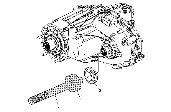
Interim 2011 model year, a new design front output shaft deflector (3) was implemented into production for second design NQF–HD/SHD and NQG–HD applications. First design 2011 model year NQF and NQG applications can be identified as not having the deflector on the front output shaft. For service, the new design front output shaft, deflector, and new design seal may be installed on current and prior model year Magna NQF–HD/SHD, NQG–LD/HD, NQH–LD/HD, and NP0 applications providing the new design front output shaft is also installed. The front output shaft deflector is to be installed using GE-8092 driver handle (1) and DT-50649 seal installer (2).
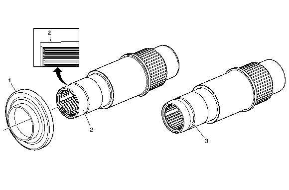
The NEW design deflector (1) can be installed onto all current and prior model year Magna RPOs NQF, NQG, NQH, and NPO applications providing the NEW design front output shaft (2) is also installed. Second design front output shafts can be identified by the machined area on the OD output end of the shaft (2). First design front output shafts can be identified by the dust boot clamp groove located (3) at the OD output end of the shaft. The NEW design slinger will NOT install onto the first design shafts. 2010 Service Parts Release Usage Change – NQH/NPO Control Actuator Levers
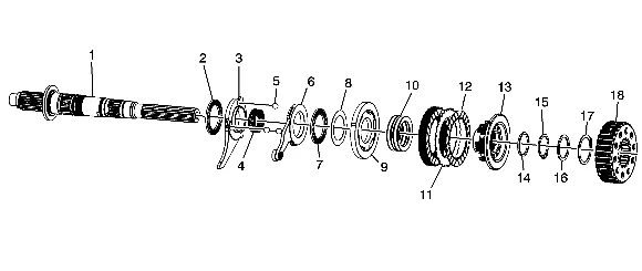
Light Duty (LD) 2007-2010 MP3023-NQH and 2010 MP3010-NP0 production transfer cases are built with LD control actuator levers (3 and 6) and are used with 13 mm (0.52 in) diameter control actuator lever balls (5) Heavy duty (HD) 2007-10 MP3024-NQH production transfer cases are built with HD control actuator levers (3 and 6) and are used with Heavy10 mm (0.39 in) control actuator lever balls. When replacement of one or both of the LD control actuator levers is required, it is necessary to replace both of the levers and all three balls with the HD components as a set. It is also necessary to re-measure and adjust clutch pack clearances as required and to perform the Transfer Case High/Low Clutch Reset. Refer to Measuring/Adjusting Clutch Assembly Height in Transfer Case Assemble, Transfer Case Description and Operation and Transfer Case High/Low Clutch Reset. Heavy duty (HD) components are the only parts available for service. 2009 Interim Model Year Design Change – NQF Two/Four Wheel Drive Actuator Cam and Shaft
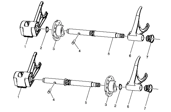
Interim 2009 model year, the high/low control actuator shaft and two/four wheel drive actuator cam designs were revised with a relocation of the shaft flange. First design 2009 transfer cases were built with first design high/low control actuator shaft (5) and cam (3). Second design 2009 transfer cases were built with second design high/low control actuator shaft (5) and cam (3). When replacing a first design control actuator shaft or cam, the second design shaft (5) and cam (3) must be installed. The second design parts are the only parts available for service.