Camshaft Position Actuator and Solenoid Valve Description
Engine Mechanical - 5.3L L84 or 6.2L L87 | Description and Operation | Document ID: 5022852 Camshaft Position Actuator and Solenoid Valve Description Camshaft
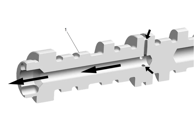
The camshaft (1) is designed to provide a lubrication path for pressurized engine oil to flow to the camshaft position (CMP) actuator. Pressurized engine oil enters the camshaft at bearing journal location number 2. Oil travels through the camshaft, out the front, and into the CMP actuator solenoid valve. Camshaft Position Actuator Valve Solenoid
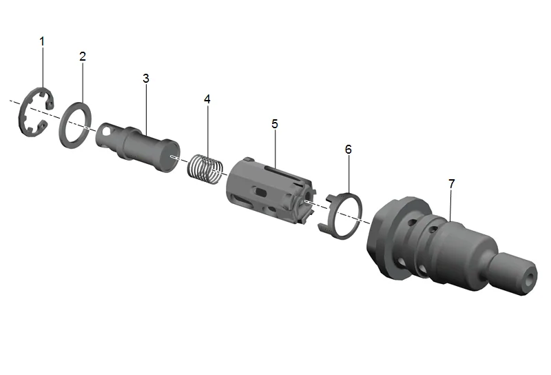
The CMP actuator solenoid valve consists of a housing (7), filter assembly (6), hydraulic unit (5), spool valve return spring (4), spool (3), washer (2), and retainer clip (1). Pressurized engine oil enters the valve and travels through the filter to the spool. Spool position is controlled by the CMP magnet and engine control module (ECM). When the spool is moved to the proper position, oil flow is directed through the valve and into the CMP actuator assembly. The CMP solenoid valve is a torque-to-yield design and should be replaced each time it is removed. Camshaft Position Actuator Magnet
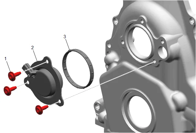
The CMP actuator magnet (2) is located in the engine front cover and is sealed by a press in place gasket (3). The CMP actuator magnet is controlled by a 12-volt 150 Hz pulse width 0–100 percent duty cycle signal from the ECM. When energized, the solenoid uses electromagnetic force on the magnet pintle to position the spool valve of the CMP solenoid valve. Camshaft Position Actuator
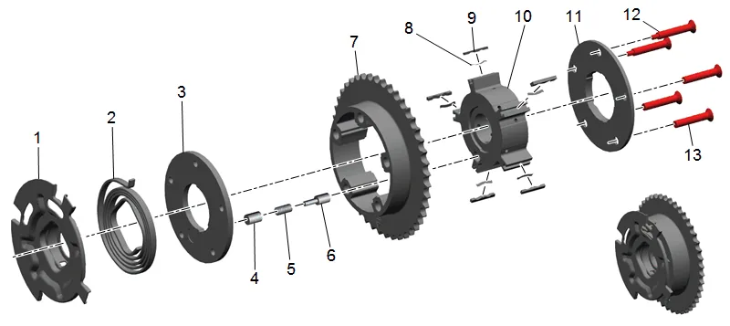
The CMP actuator is an integrated rotor vane type design that hydraulically changes angle or timing of the camshaft relative to crankshaft position. The CMP actuator allows earlier or later intake and exhaust valve opening during the 4-stroke engine cycle. The CMP actuator cannot vary the duration of valve opening or valve lift. The CMP actuator is to be serviced as an assembly. Camshaft Actuator System Description The CMP actuator consists of the CMP reluctor wheel (1), return spring (2), front cover (3), locking pin (4), locking pin spring (5), cartridge (6), stator (7), vane spring (8), sealing lips (9), rotor (10), sealing cover and thrust plate (11), and bolts (12). Camshaft Position Actuator System Operation
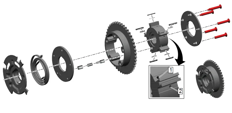
A CMP actuator dynamically changes valve timing events relative to piston timing by controlling camshaft position. This is sometimes referred to as variable valve timing or camshaft phasing. Variable valve timing or camshaft phasing does not change duration or lift. By advancing camshaft timing, an improvement in low end torque can be achieved. By retarding camshaft timing slightly, an improvement in high end power can be achieved. By retarding camshaft timing significantly, an improvement in light load fuel economy can be achieved. There are 5 cavities divided by vanes within the CMP actuator. When oil is directed to the advance cavities (1), the camshaft timing is advanced. When oil is directed to the retard cavities (2), the camshaft timing is retarded. When oil is directed to both cavities, the camshaft is held stationary.
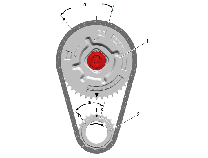
The CMP actuator (1) has a 62 degree (a) range of authority at the crankshaft (31 degrees (d) at the camshaft). With the engine not running and no engine oil pressure to the CMP actuator (1), the high tension spring positions camshaft timing at the 7 degree (c) advanced park position at the crankshaft (3.5 degrees (f) at the camshaft). During normal engine operation, and based on performance requirements, the ECM may adjust camshaft timing, as required, within a range from 7 degrees (c) advanced at the crankshaft (3.5 degrees (f) at the camshaft) to 55 degrees (b) retard at the crankshaft (27.5 degrees (e) at the camshaft). Camshaft Position Actuator System Lubrication Flow and Actuator Operation
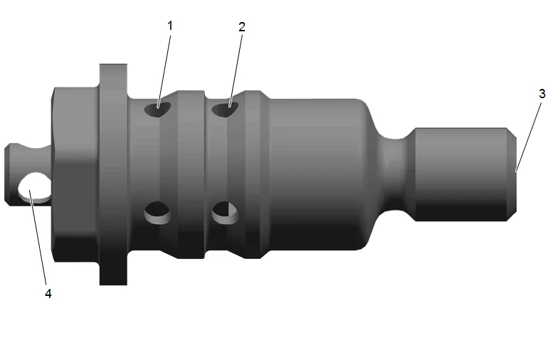
- Oil flows from the camshaft into the valve inlet (3) through the internal check ball and filter.
- Valve spool position directs oil out of the valve advance (1) or retard (2) ports to the actuator.
- The valve may also, under certain conditions, be positioned in a neutral position with alternating low, balanced oil flow between the advance and retard passages of the actuator.
- Excess oil is directed out the front port of the valve (4) and down to the oil pan.
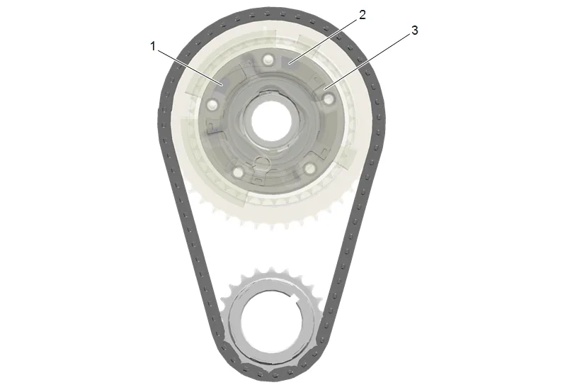
- Pressurized oil enters the retard cavities (3) of the actuator and moves the park pin (2) from the locked position.
- As pressure increases within the retard cavities (3), the rotor and camshaft rotate counter clockwise retarding valve timing.
- As the duty cycle decreases, the spool is repositioned and oil is sent to the advance cavities (1), rotating the rotor and camshaft clockwise, advancing valve timing. With a 0 percent duty cycle signal to the magnet, the spool is positioned in the fully extended position and there is full flow to the advance cavities of the actuator. As duty cycle increases to near 50 percent, flow to the advance cavities is decreased. With a 50 percent duty cycle, the spool is positioned neutral, with no flow to either the advance and retard cavities. With a 51–100 percent duty cycle, the spool is positioned to provide oil flow to retard cavities. As the duty cycle increases, the flow to retard cavities increases. With a 100 percent duty cycle, there is full flow to the retard cavities of the actuator. The above duty cycle percentage values are only a guideline, as the actual duty cycle values may vary based on engine oil temperature, solenoid magnet coil temperature, magnet coil resistance, and other specifics. Camshaft Position Actuator Park Position Verification
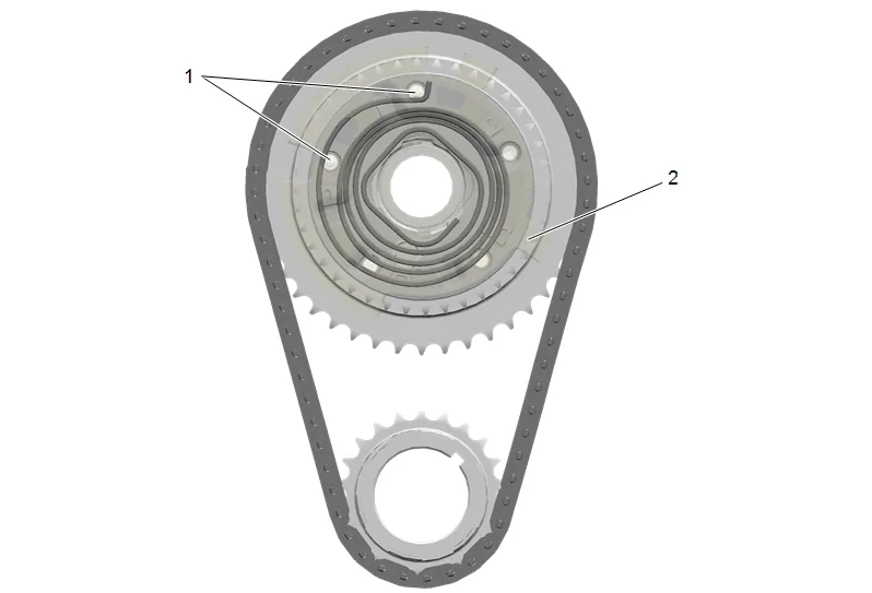
The CMP actuator can be visually inspected to determine if the tension spring has returned the reluctor wheel and rotor to the park position. With the reluctor wheel returned to the proper parked position, the pins (1) will be positioned in the slots of the reluctor wheel (2) as shown. Camshaft Position Actuator Actuator Handling Safety
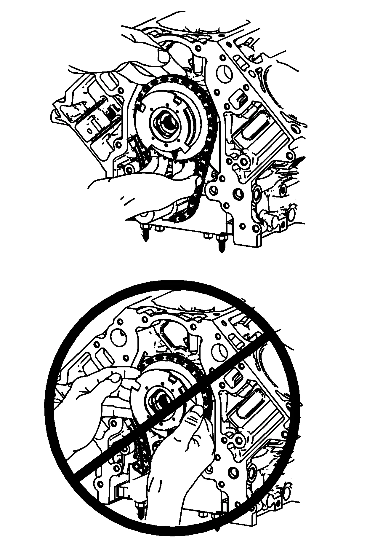
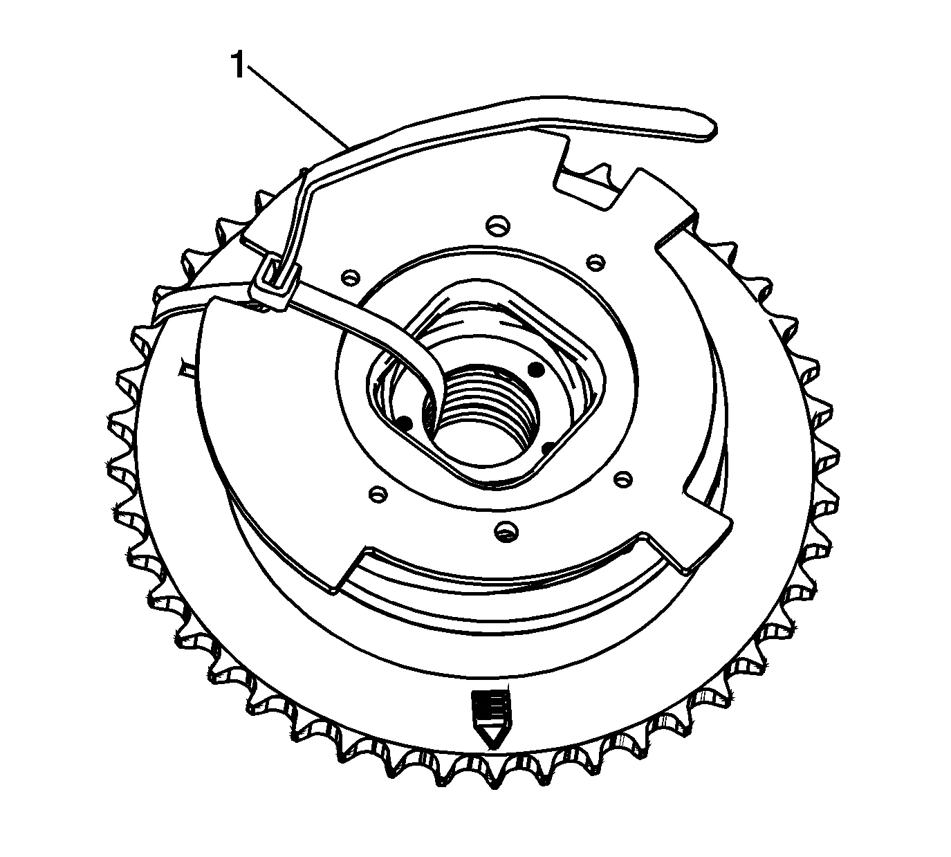
Install tie wrap (1) to retain the reluctor wheel to the sprocket. The reluctor wheel is mounted to the actuator body with 3 roll pins.