Cooling System Draining and Filling (GE 47716 L84, L87)
Special Tools GE-26568 Coolant and Battery Tester GE-42401-A Radiator Cap and Surge Tank Test Adapter GE-47716 Vac-N-Fill Coolant Refill Tool Equivalent regional tools: Special Tools Draining Procedure
- Park the vehicle on a level surface.
- Remove the radiator surge tank cap
- Raise and support the vehicle. Lifting and Jacking the Vehicle
- Attach a rubber hose to the radiator drain port to guide the coolant into the drain pan.
- Place a drain pan under the drain cock.
- Rotate the radiator drain cock counterclockwise to open.
- Drain the cooling system.
- Rotate the radiator drain cock clockwise to close.
- Disconnect the rubber hose.
- Remove the drain pan.
- Lower the vehicle.
- Inspect the coolant.
- If the coolant is discolored, perform the flushing procedure. Flushing Vac-N-Fill Procedure
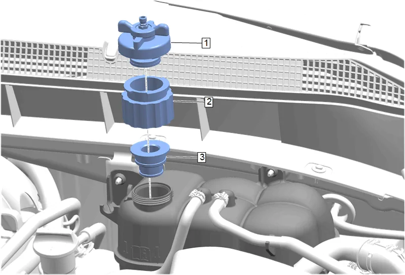
- GE-42401-2 Adapter Assembly (3) » Install
- GE-42401-3 Radiator Test Adapter - Female (2) » Install
- GE-47716-8 Vac-N-Fill Cap (1) » Install
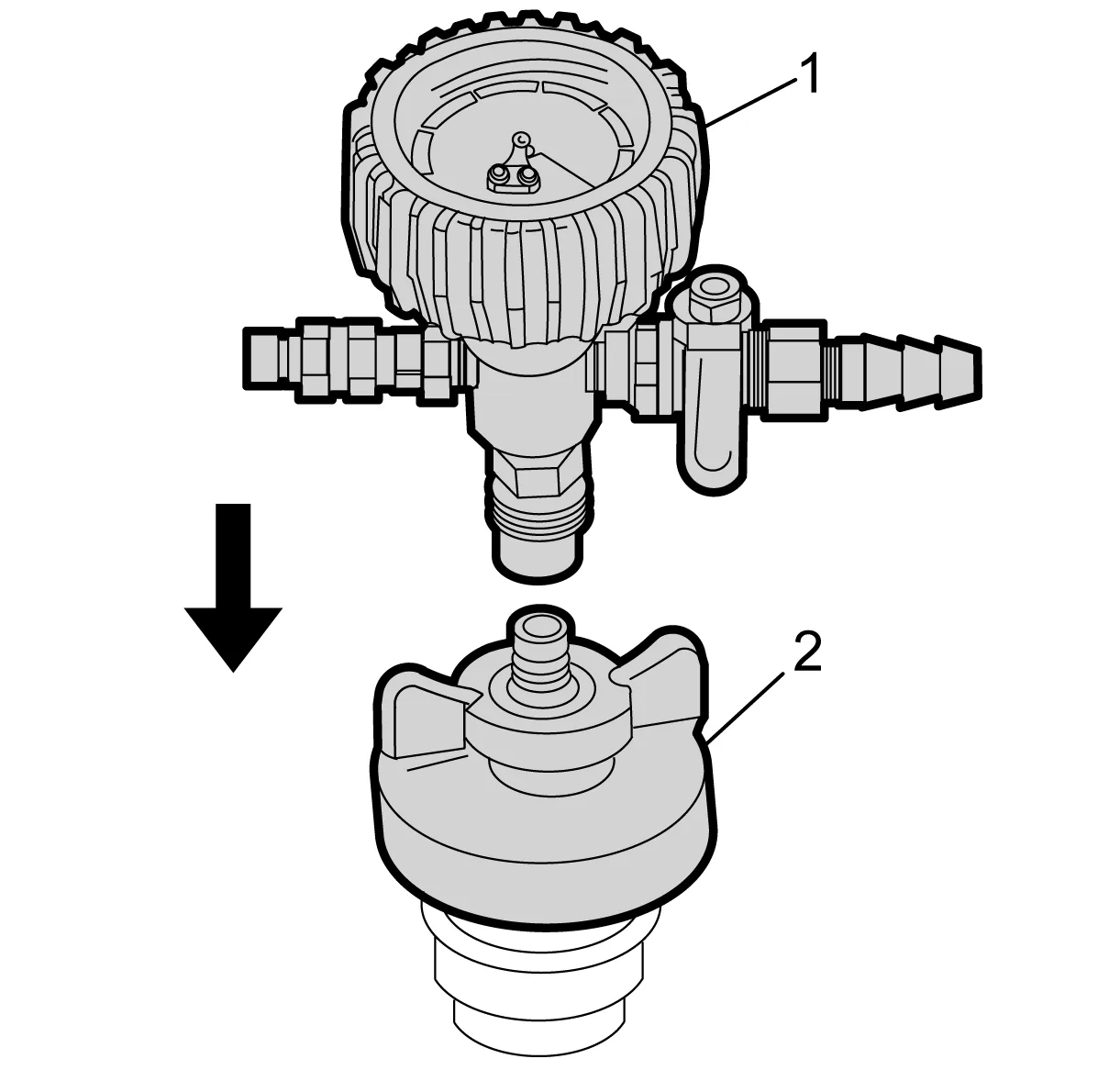
- Attach the vacuum gauge assembly (1) to the Vac-N-Fill cap (2).
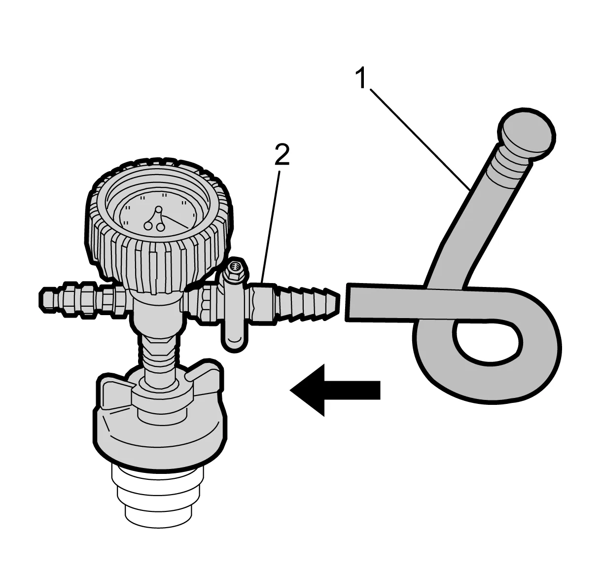
- Attach the fill hose (1) to the barb fitting on the vacuum gauge assembly (2). Ensure that the valve is closed.
- Prepare a 50/50 mixture of DEX-COOL antifreeze and clean, drinkable water in a quantity that is slightly greater than the maximum capacity of the cooling system. Adhesives, Fluids, Lubricants, and Sealers Approximate Fluid Capacities
- Inspect the concentration of the coolant mixture using GE-26568 Coolant and Battery Fluid Tester.
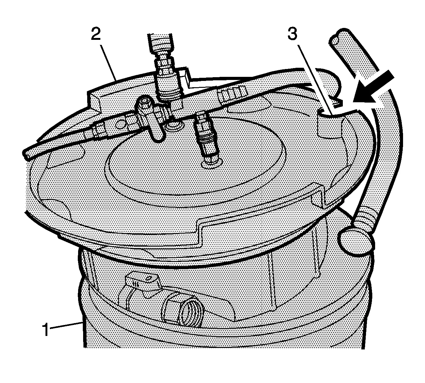
- Pour the coolant mixture into the graduated reservoir (1).
- Place the fill hose in the graduated reservoir (1).
- Install the vacuum tank (2) on the graduated reservoir with the fill hose routed through the cut-out area (3) in the vacuum tank.
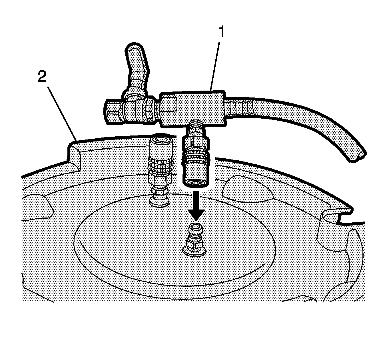
- Attach the venturi assembly (1) to the vacuum tank (2).
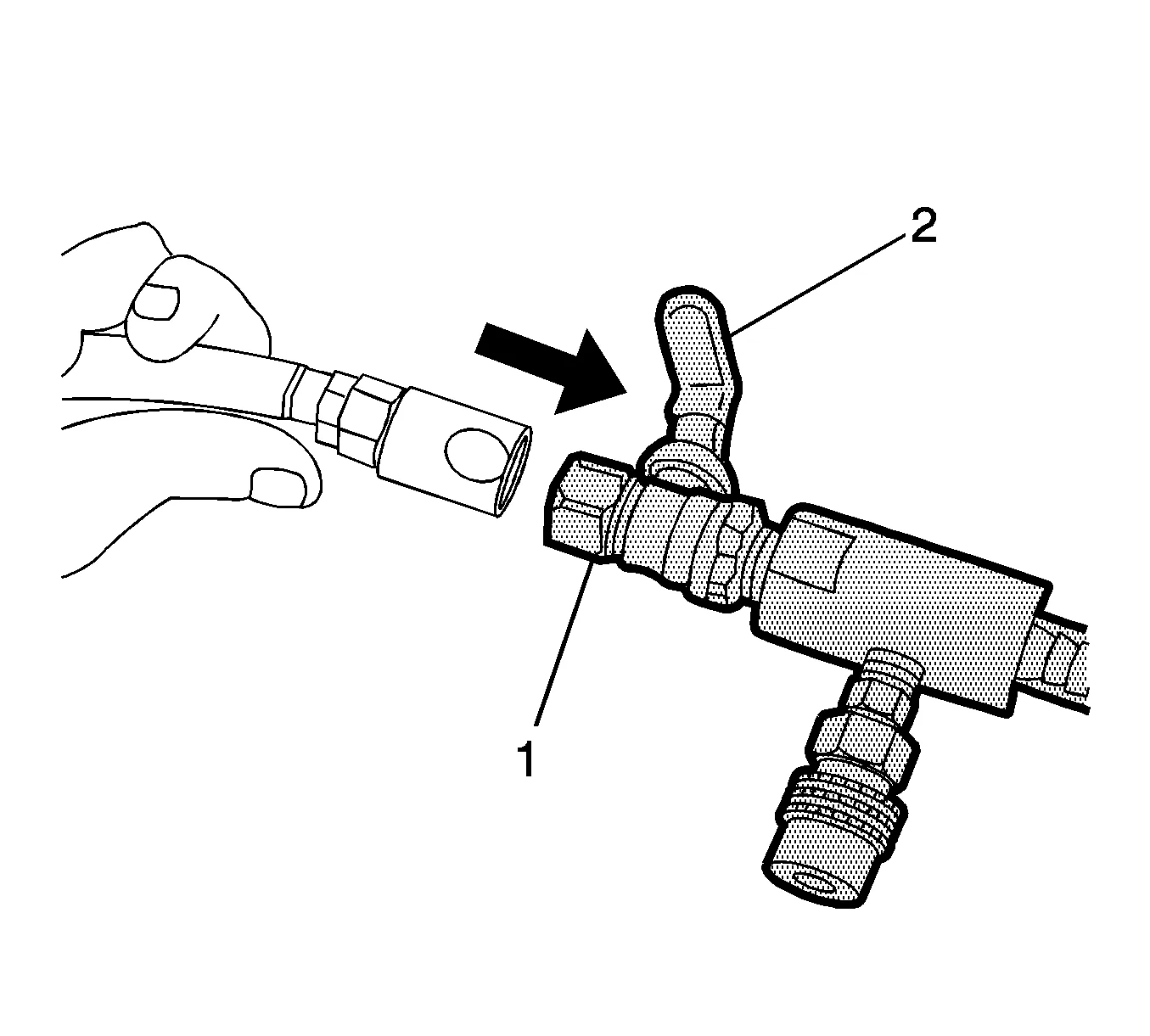
- Attach a shop air hose to the venturi assembly (1). Ensure the valve (2) on the venturi assembly is closed.
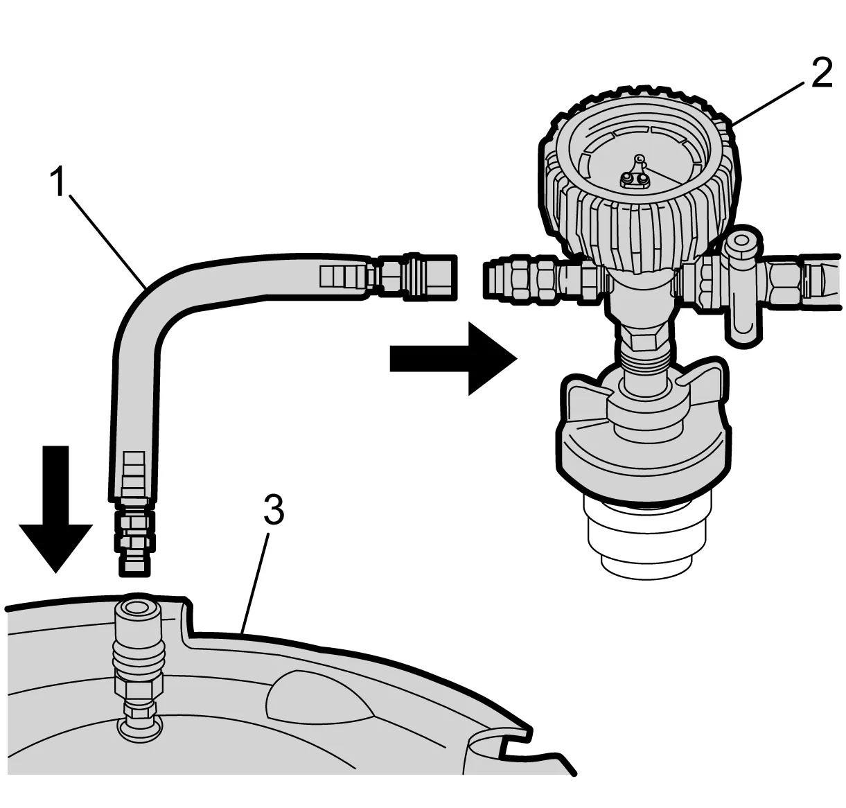
- Attach the vacuum hose (1) to the vacuum gauge assembly (2) and the vacuum tank (3).
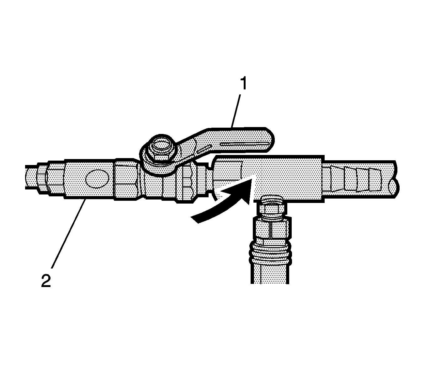
- Open the valve (1) on the venturi assembly (2). The vacuum gauge will begin to rise and a hissing noise will be present.
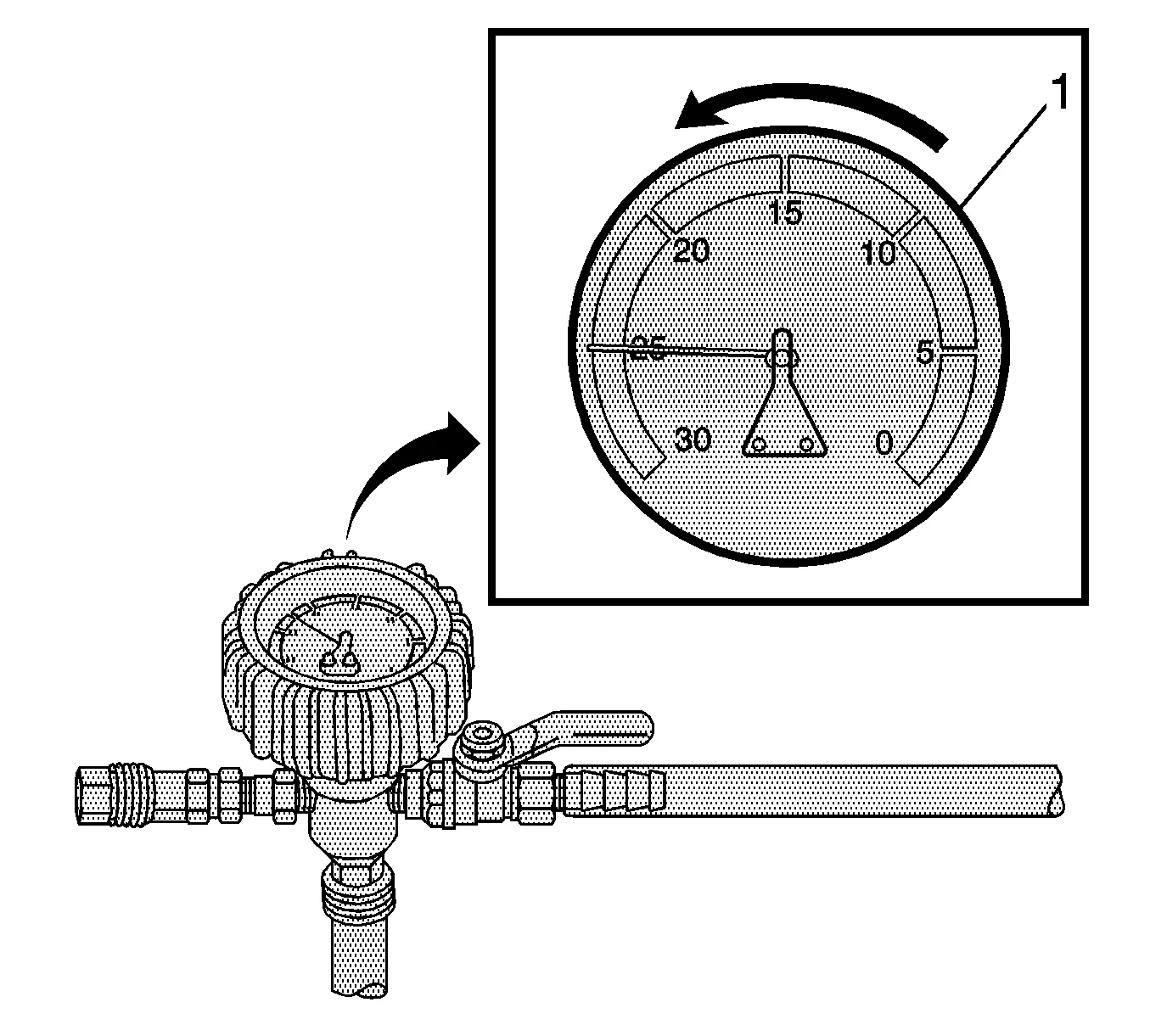
- Continue to draw vacuum until the needle stops rising (1). This should be 610-660 mm Hg (24-26 in Hg). Coolant hoses may start to collapse. This is normal due to vacuum draw.
- To aid in the fill process, position the graduated reservoir above the coolant fill port.
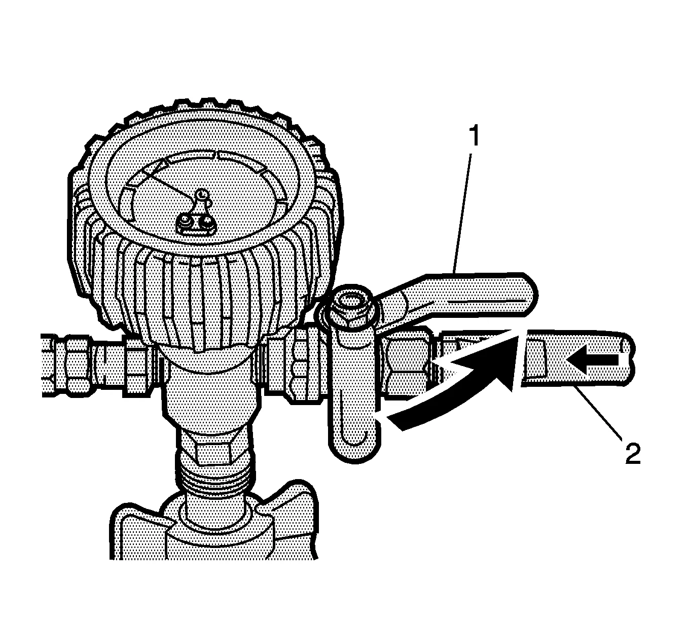
- Slowly open the valve (1) on the vacuum gauge assembly (2). When the coolant reaches the top of the fill hose, close the valve. This will eliminate air from the fill hose.
- Close the valve on the venture assembly.
- If there is a suspected leak in the cooling system, allow the system to stabilize under vacuum and monitor for vacuum loss. If vacuum loss is observed, refer to Loss of Coolant.
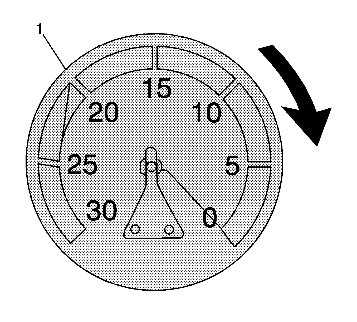
- Open the valve on the vacuum gauge assembly. The vacuum gauge will drop as coolant is drawn into the system.
-
Once the vacuum gauge reaches zero (1), close the valve on the vacuum gauge assembly and repeat steps 13–20.
-
GE-47716-8 Vac-N-Fill Cap (1) » Remove
-
GE-42401-3 Radiator Test Adapter - Female (2) » Remove
-
GE-42401-2 Adapter Assembly (3) » Remove
-
Ensure that the coolant system is at the correct level within the coolant surge tank.
-
Fill the cooling system to the proper level. Adhesives, Fluids, Lubricants, and Sealers
-
If the coolant system level is over the maximum level allowed within surge tank, perform steps 29–31 until correct level is achieved.
- Detach the vacuum hose from the vacuum gauge assembly.
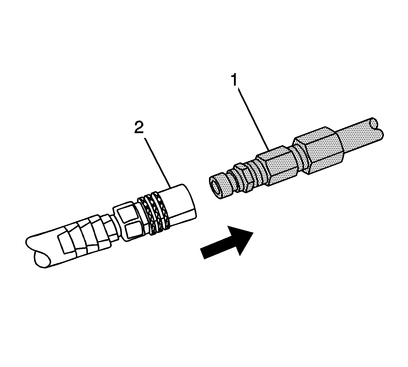
- Attach the extraction hose (1) to the vacuum hose (2).
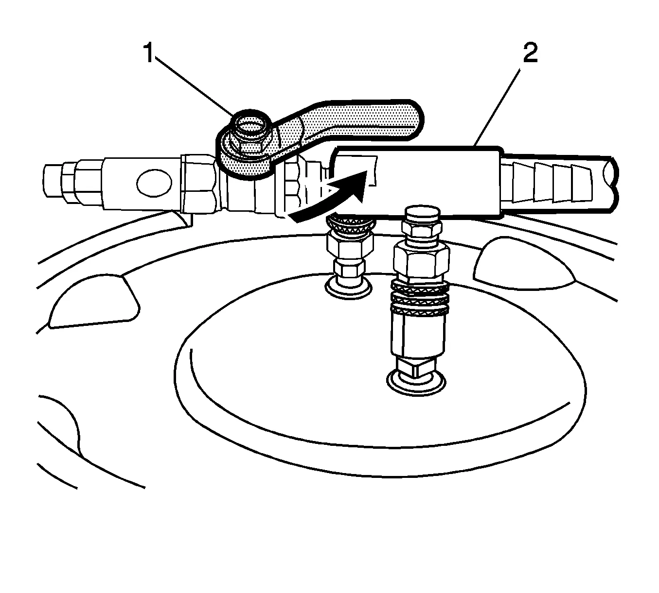
- Open the valve (1) on the venturi assembly (2) to start a vacuum draw.
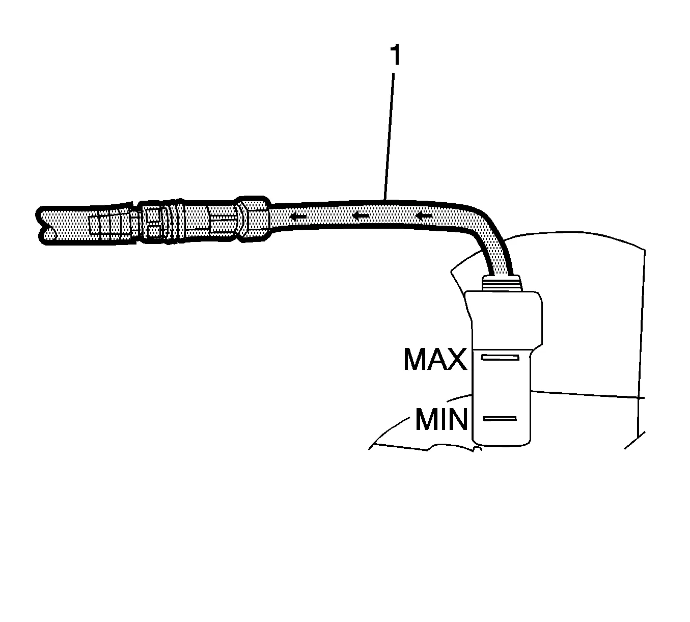
- Use the extraction hose (1) to draw out coolant to the proper level.
- The vacuum tank has a drain valve on the bottom of the tank. Open the valve to drain coolant from the vacuum tank into a suitable container for disposal.
- Install the radiator surge tank cap.