Transfer Case Assembly Replacement (L84, L87 with F47) (1)
Transfer Case Assembly Replacement (L84, L87 with F47) Single Use Fasteners and Components Exhaust System Seal [2x] Transfer Case Front Output Shaft Boot Clamp Transfer Case Adapter Gasket Special Tools DT-35910 Drive Axle Seal Clamp Pliers Equivalent regional tools: Special Tools
- Place the air system in service mode.
- Place the transmission in neutral service mode. Neutral Service Mode
- Disconnect the battery negative cable. Battery Negative Cable Disconnection and Connection
- Front Wheelhouse Liner - Left Side and Right Side » Remove — Front Wheelhouse Liner Replacement
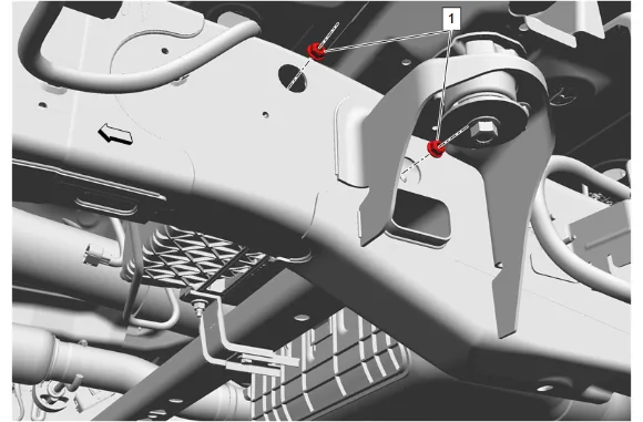
- Evaporative Emission Canister Bracket Nut (1) » Loosen [2x]
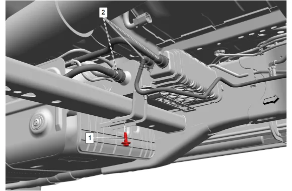
- Evaporative Emission Canister Bracket Bolt (1) » Remove
- Evaporative Emission Hose (2) » Disconnect [3x] — Plastic Collar Quick Connect Fitting Service
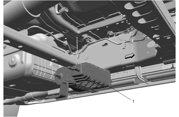
- Evaporative Emission Canister (1) » Remove
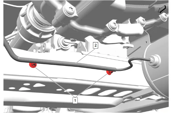
- Unclip the 2 air line retainers (1) and reposition the air line (2).
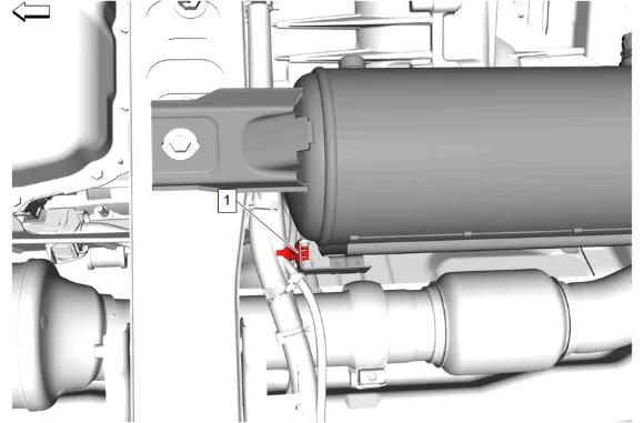
- If equipped, remove the chassis wire harness clip (1) from the automatic level control air supply reservoir.
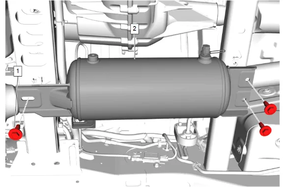
- Remove the 3 automatic level control air compressor bolts (1).
- Automatic Level Control Air Supply Reservoir (2) » Reposition
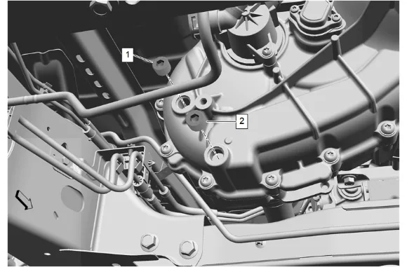
- Drain the fluid from the transfer case. Transfer Case Fluid Replacement
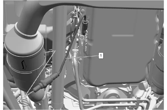
- Electrical Connector @ Heated Oxygen Sensor Bank 1 Sensor 2 » Disconnect
- Using a suitable tool, remove the heated oxygen sensor bank 1 sensor 2 (1).
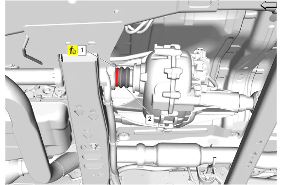
- Transfer Case Front Output Shaft Boot Clamp (1) @ Front Axle Propeller Shaft » Remove and DISCARD
- Reposition the transfer case front output shaft boot (2) and mark a reference point between the front axle propeller shaft and the transfer case front output shaft.
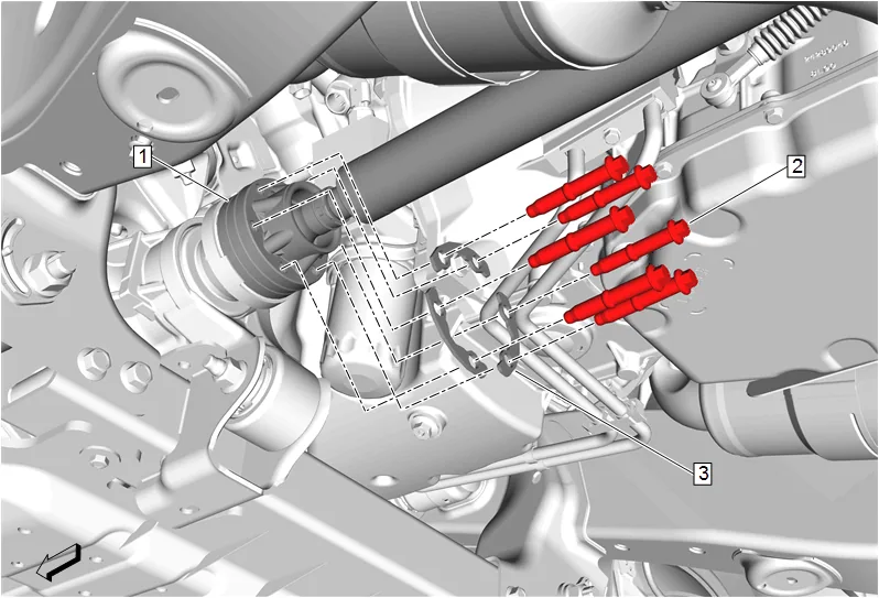
- Mark a reference point between the front axle propeller shaft (1) and the front differential drive pinion gear yoke.
- Front Axle Propeller Shaft Bolt (2) » Remove [6x]
- Front Axle Propeller Shaft Washer (3) » Remove [3x]
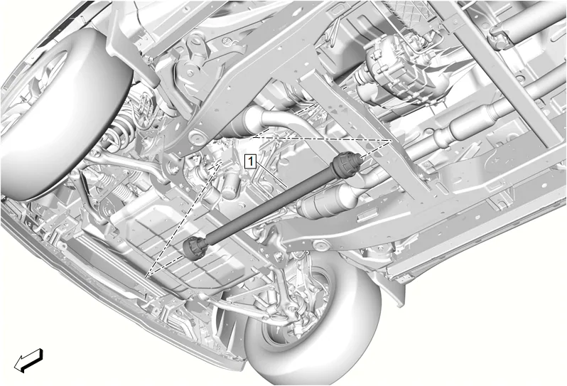
- Front Axle Propeller Shaft (1) » Remove
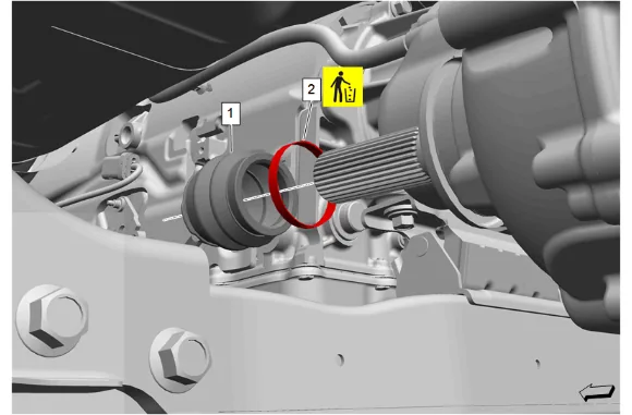
- Transfer Case Front Output Shaft Boot Clamp (2) @ Transfer Case » Remove and DISCARD
- Transfer Case Front Output Shaft Boot (1) » Remove
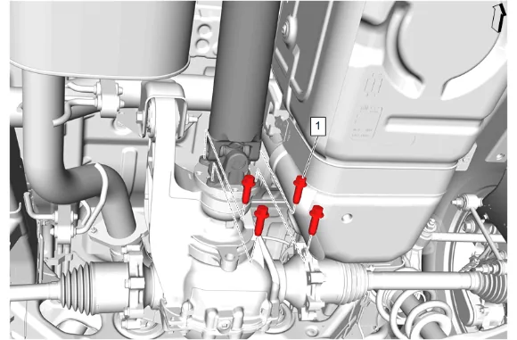
- Mark the relationship of the propeller shaft to the differential drive pinion gear yoke.
- Rear Propeller Shaft Bolt (1) » Remove [4x]
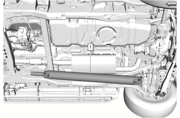
- Propeller Shaft (1) » Remove
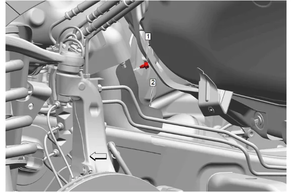
- Exhaust Heat Shield Bolt (1) » Remove
- Exhaust Front Pipe Heat Shield (2) » Remove
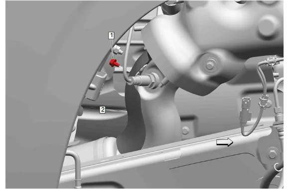
- Exhaust Heat Shield Bolt (1) » Remove
- Exhaust Front Pipe Heat Shield (2) » Remove
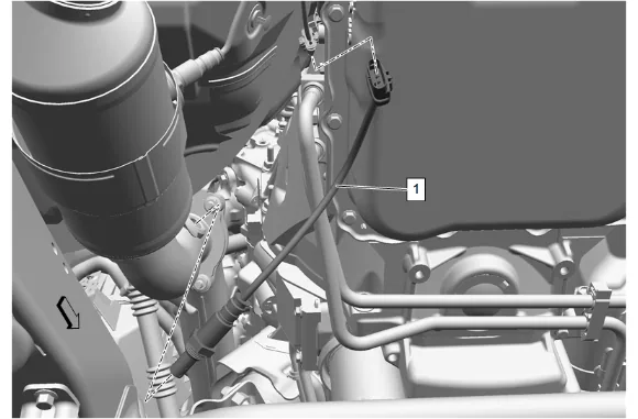
- Electrical Connector @ Heated Oxygen Sensor Bank 1 Sensor 1 » Disconnect
- Remove the heated oxygen sensor bank 1 sensor 1 (1) using a suitable tool.
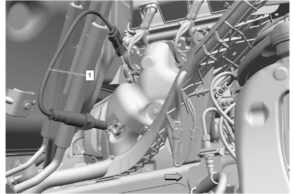
- Electrical Connector @ Heated Oxygen Sensor Bank 2 Sensor 1 » Disconnect
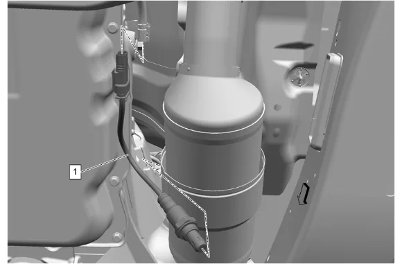
- Electrical Connector @ Heated Oxygen Sensor Bank 2 Sensor 2 » Disconnect
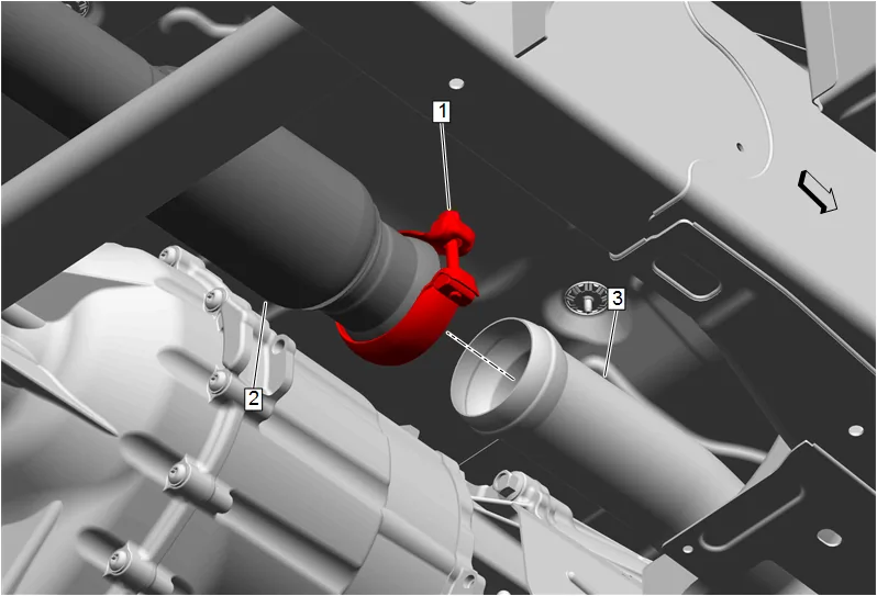
- Exhaust Pipe Clamp (1) » Loosen
- Exhaust Muffler (2) @ Three-Way Catalytic Converter (3) » Separate
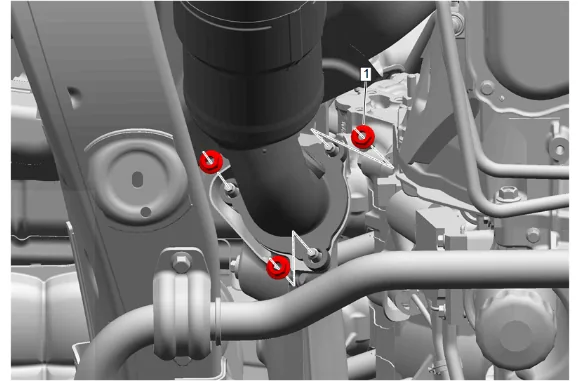
- Exhaust Front Pipe Nut (1) - Left Side » Remove [3x]
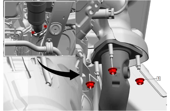
- Exhaust Front Pipe Nut (1) - Right Side » Remove [3x]
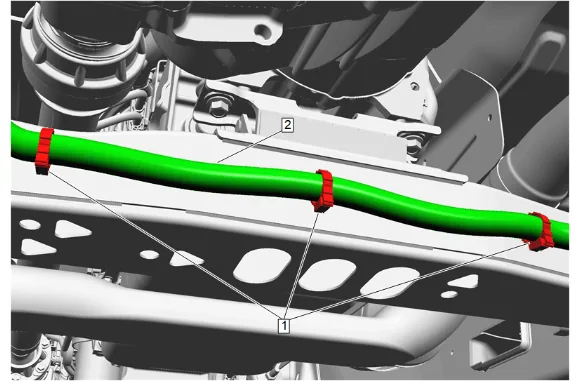
- { If equipped } Remove the wiring harness (2) from the 3 wiring harness retainers (1) and reposition the wiring harness as necessary.
- Support the transmission with a suitable jack.
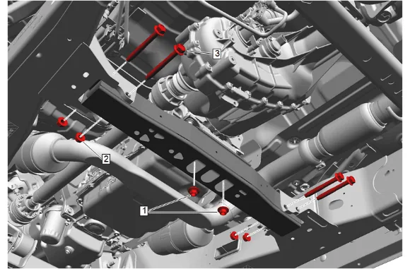
- Transmission Mount Nut (1) » Remove [2X]
- Transmission Support Crossmember Nut (2) » Remove [4x]
- Transmission Support Crossmember Bolt (3) » Remove [4x]
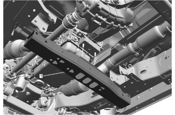
- Transmission Support Crossmember (1) » Remove
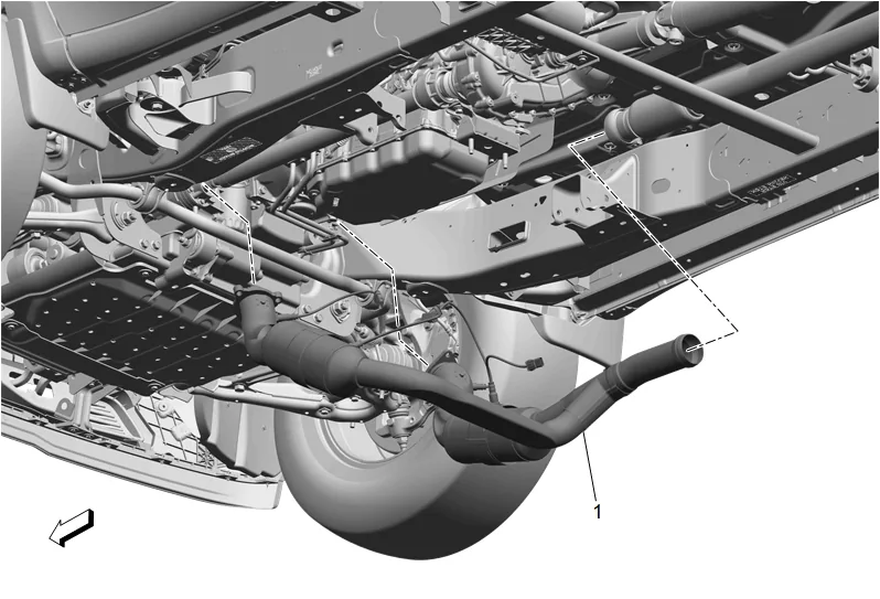
- Three-Way Catalytic Converter (1) » Remove

- Exhaust System Seal - Left Side (1) » Remove and DISCARD
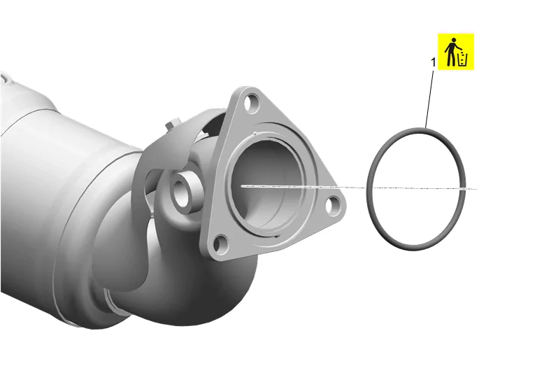
- Exhaust System Seal - Right Side (1) » Remove and DISCARD
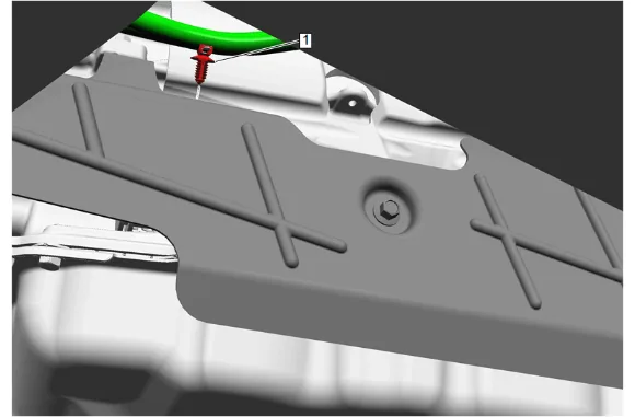
- Disconnect the transmission wiring harness retainer (1) and reposition the harness as necessary.
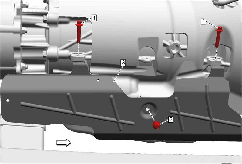
- Transmission Heat Shield Bolt (2) » Remove
- Transmission Heat Shield Bolt (1) » Remove [2x]
- Transmission Heat Shield (3) » Remove
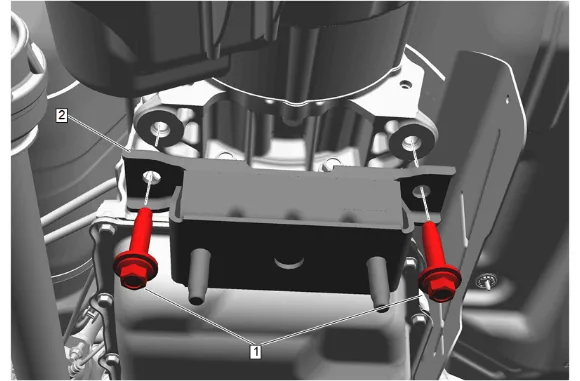
- Transmission Mount Bolt (1) » Remove [2x]
- Transmission Mount (2) » Remove
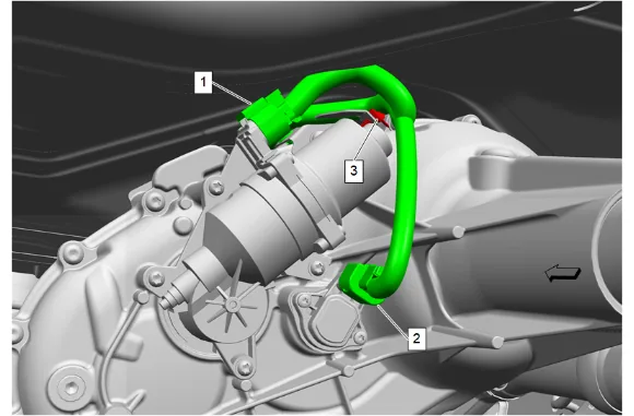
- Disconnect the transfer case two/four wheel drive actuator electrical connector (1).
- Disconnect the transfer case two/four wheel drive actuator position sensor electrical connector (2).
- Remove the wiring harness retainer (3) from the transfer case and position the wiring harness out of the way.
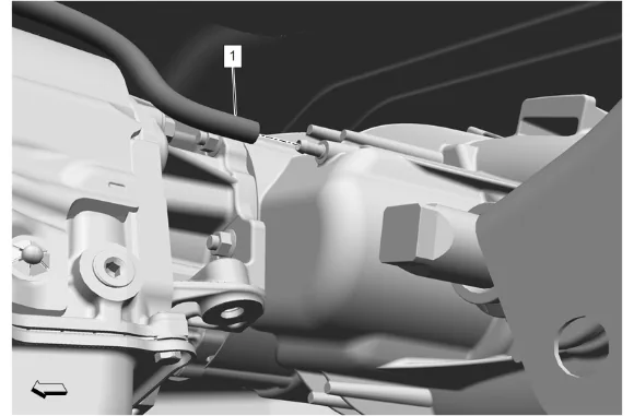
- Transfer Case Vent Hose (1) » Remove
- Using a suitable transmission jack, support the transfer case.
- Using suitable straps or chains, secure the transfer case to the transmission jack.
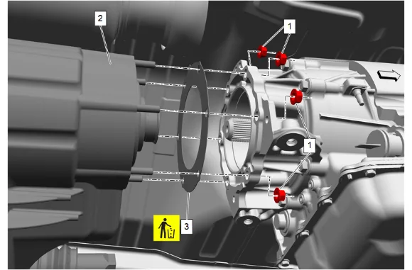
-
Transfer Case Nut (1) » Remove [6x]
-
Transfer Case (2) » Remove
-
Transfer Case Adapter Gasket (3) » Remove and DISCARD Installation Procedure
-
Apply grease the length of the splines even with the top of the splines. Adhesives, Fluids, Lubricants, and Sealers
-
Transfer Case Adapter Gasket (3) » Install NEW
-
Transfer Case (2) » Install
-
Transfer Case Nut (1) » Install and tighten [6x] — Fastener Specifications
-
Remove the transmission jack from the transfer case.
-
Transfer Case Vent Hose (1) » Install
-
Reposition the wiring harness and install the wiring harness retainer (3) in to the transfer case.
-
Connect the transfer case two/four wheel drive actuator position sensor electrical connector (2).
-
Connect the transfer case two/four wheel drive actuator electrical connector (1).
-
Transmission Mount (2) » Install
-
If NEW threaded components are being installed, loosen the adhesive using a metal pick or similar tool before proceeding. If threaded components are reused, prepare the threaded components using the following steps: 11.1. Remove any loose cured adhesive from the external threads of the components using a lint free cloth. 11.2. Thread the cleaned components into the internal mating threads and remove to loosen trapped cured adhesive. 11.3. Apply thread locking adhesive to the external threads of the components. Adhesives, Fluids, Lubricants, and Sealers 11.4. Ensure there are no gaps in the thread locking adhesive once applied to the component.
-
Transmission Mount Bolt (1) » Install and tighten [2x] — Fastener Specifications
-
Transmission Heat Shield (3) » Install
-
If NEW threaded components are being installed, loosen the adhesive using a metal pick or similar tool before proceeding. If threaded components are reused, prepare the threaded components using the following steps: 14.1. Remove any loose cured adhesive from the external threads of the components using a lint free cloth. 14.2. Thread the cleaned components into the internal mating threads and remove to loosen trapped cured adhesive. 14.3. Apply thread locking adhesive to the external threads of the components. Adhesives, Fluids, Lubricants, and Sealers 14.4. Ensure there are no gaps in the thread locking adhesive once applied to the component.
-
Transmission Heat Shield Bolt (2) » Install and tighten — Fastener Specifications
-
Transmission Heat Shield Bolt (1) » Install and tighten [2x] — Fastener Specifications
-
Reposition the transmission wiring harness and connect the wiring harness retainer (1).
-
Exhaust System Seal - Right Side (1) » Install NEW
-
Exhaust System Seal - Left Side (1) » Install NEW
-
Three-Way Catalytic Converter (1) » Install
-
Transmission Support Crossmember (1) » Install
-
Transmission Support Crossmember Bolt (3) » Install [4x]
-
Transmission Support Crossmember Nut (2) » Install and tighten [4x] — Fastener Specifications
-
Transmission Mount Nut (1) » Install and tighten [2x] — Fastener Specifications
-
Remove the transmission jack.
-
{ If equipped } Install the wiring harness (2) as necessary then install the harness into the 3 wiring harness retainers (1).
-
Exhaust Front Pipe Nut - Right Side (1) » Install and tighten [3x] — Fastener Specifications
-
Exhaust Front Pipe Nut - Left Side (1) » Install and tighten [3x] — Fastener Specifications
-
Exhaust Muffler (2) @ Three-Way Catalytic Converter (3) » Connect
-
Exhaust Pipe Clamp (1) » Tighten — Fastener Specifications
-
Electrical Connector @ Heated Oxygen Sensor Bank 2 Sensor 2 » Connect
-
Electrical Connector @ Heated Oxygen Sensor Bank 2 Sensor 1 » Connect
-
Using a suitable tool, install and tighten the heated oxygen sensor bank 1 sensor 1 (1). Fastener Specifications
-
Electrical Connector @ Heated Oxygen Sensor Bank 1 Sensor 1 » Connect
-
Exhaust Front Pipe Heat Shield (2) » Install
-
Exhaust Heat Shield Bolt (1) » Install and tighten — Fastener Specifications
-
Exhaust Front Pipe Heat Shield (2) » Install
-
Exhaust Heat Shield Bolt (1) » Install and tighten — Fastener Specifications
-
Propeller Shaft (1) » Install
-
Align the reference marks made between the rear wheel drive shaft flange and the front and rear propeller shaft.
-
If NEW threaded components are being installed, loosen the adhesive using a metal pick or similar tool before proceeding. If threaded components are reused, prepare the threaded components using the following steps: 41.1. Remove any loose cured adhesive from the external threads of the components using a lint free cloth. 41.2. Thread the cleaned components into the internal mating threads and remove to loosen trapped cured adhesive. 41.3. Apply thread locking adhesive to the external threads of the components. Adhesives, Fluids, Lubricants, and Sealers 41.4. Ensure there are no gaps in the thread locking adhesive once applied to the component.
-
Rear Propeller Shaft Bolt (1) » Install and tighten [4x] — Fastener Specifications
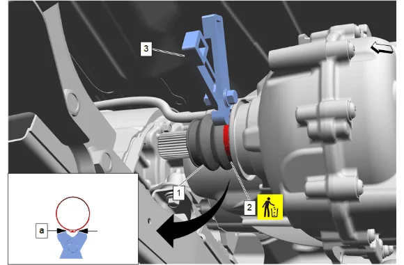
- Transfer Case Front Output Shaft Boot (1) » Install
- Using the DT-35910 Drive Axle Seal Clamp Pliers (3), install and crimp the NEW transfer case front output shaft boot clamp (2) until the gap at the base of the ear (a) is 1.5 mm (0.059 in).
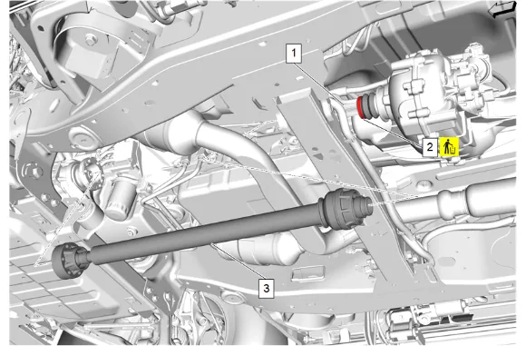
-
Apply a thin layer of grease to the splines of the transfer case front output shaft (1). Adhesives, Fluids, Lubricants, and Sealers
-
Loosely install a NEW transfer case front output shaft boot clamp (2) to the transfer case front output shaft boot groove.
-
Align the reference marks made between the transfer case front output shaft and the front axle propeller shaft.
-
Front Axle Propeller Shaft (3) » Install
-
If NEW threaded components are being installed, loosen the adhesive using a metal pick or similar tool before proceeding. If threaded components are reused, prepare the threaded components using the following steps: 49.1. Remove any loose cured adhesive from the external threads of the components using a lint free cloth. 49.2. Thread the cleaned components into the internal mating threads and remove to loosen trapped cured adhesive. 49.3. Apply thread locking adhesive to the external threads of the components. Adhesives, Fluids, Lubricants, and Sealers 49.4. Ensure there are no gaps in the thread locking adhesive once applied to the component.
-
Align the reference marks made between the front axle propeller shaft (1) and the front differential drive pinion gear yoke.
-
Front Axle Propeller Shaft Washer (3) » Install [3x]
-
Install the 6 front axle propeller shaft bolts (2) and tighten in a crisscross pattern. Fastener Specifications
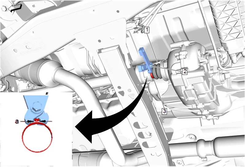
-
Ensure the transfer case front output shaft boot (1) is fully engaged into the groove of the transfer case front output shaft.
-
Using the DT-35910 Drive Axle Seal Clamp Pliers (2), crimp the transfer case front output shaft boot clamp (3) until the gap (a) at the base of the ear is 1.5 mm (0.059 in).
-
Using a suitable tool, install and tighten the heated oxygen sensor bank 1 sensor 2 (1). Fastener Specifications
-
Electrical Connector @ Heated Oxygen Sensor Bank 1 Sensor 2 » Connect
-
Fill the transfer case to the bottom of the fill plug hole with the recommended fluid. Transfer Case Fluid Replacement
-
Evaporative Emission Canister (1) » Install
-
Evaporative Emission Hose (2) » Connect [3x] — Plastic Collar Quick Connect Fitting Service
-
Evaporative Emission Canister Bracket Bolt (1) » Install and tighten — Fastener Specifications
-
Evaporative Emission Canister Bracket Nut (1) » Tighten [2x] — Fastener Specifications
-
Automatic Level Control Air Supply Reservoir (2) » Install
-
Install the 3 automatic level control air compressor bolts (1) and tighten. Fastener Specifications
-
If equipped, install the chassis wire harness clip (1) to the automatic level control air supply reservoir.
-
Install the air line (2) and clip the 2 air line retainers (1).
-
Front Wheelhouse Liner - Left Side and Right Side (1) » Install — Front Wheelhouse Liner Replacement
-
Connect the battery negative cable. Battery Negative Cable Disconnection and Connection
-
After replacing the transfer case, perform the transfer case range actuator learn. Transfer Case Range Actuator Learn
-
Inspect for Leaks
-
Take the air system out of service mode.