Propeller Shaft Runout Measurement
Vibration Diagnosis and Correction | Diagnostic Information and Procedures | Document ID: 5044700 Special Tools GE-7872 Magnetic Base Dial Indicator Set, or equivalent GE-8001 Dial Indicator Set, or equivalent For equivalent regional tools. Special Tools and Equipment
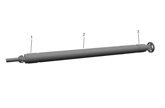
- Raise and support the vehicle. On vehicles with solid axles, ensure that the drive axle is supported at ride height – vehicle body supported by suspension components. Ensure the wheels are free to rotate. Lifting and Jacking the Vehicle
- Place the transmission in NEUTRAL.
- Clean the circumference of the propeller shaft(s) of any debris and/or undercoating along the front (1), center (2), and rear (3) positions.
- Inspect the propeller shaft(s) for dents, damage, and/or missing weights. Any propeller shaft that is dented or damaged requires replacement.
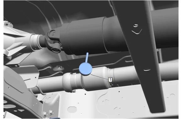
-
For 1-piece and 2-piece propeller systems, mount the GE-7872 Magnetic Base Dial Indicator Set or the GE-8001 Dial Indicator Set (1) to the vehicle underbody or to a service stand positioned just clear of the universal joint yoke weld and correction balance weight on the propeller shaft.
-
Rotate the drive axle pinion flange, torque tube input flange, transmission output, or transfer case output flange by hand while taking runout measurements of the propeller shaft(s). The propeller shaft will rotate more easily in one direction than in the other. If necessary, the tire and wheel assemblies and even the brake caliper assemblies can be positioned and supported aside from the drive axle to provide easier rotation of the propeller shaft(s).
-
For all propeller systems, measure and record the runout at each universal joint welded yoke location (1, 3) and at the center (2) of each propeller shaft.
-
For 1-piece propeller systems, proceed to step 10.
-
Compare the propeller shaft runout measurements recorded to the runout tolerance specifications. Propeller Shaft Runout Specifications
-
If the propeller system has a universal joint at the transmission or transfer case output flange, and if the propeller shaft runout measurements exceed runout tolerance specifications for that propeller shaft at that location perform the following: 10.1. Inspect the deflection of the transmission or transfer case output shaft for indications of a worn or damaged bushing which could be affecting the runout of the propeller shaft. A leaking transmission or transfer case output shaft seal may be an indication of an output shaft bushing concern. 10.2. If the transmission or transfer case output shaft bushing is found to be worn or damaged, the bushing must be replaced before proceeding. 10.3. If the transmission or transfer case output shaft bushing was replaced; re-measure and record the runout of the propeller shaft at the same locations measured previously. 10.4. Compare the propeller shaft runout re-measurements recorded to the runout tolerance specifications. 10.5. If the propeller shaft runout re-measurements still exceed runout tolerances at the same location or at the stub shaft, if part of the front shaft, the propeller shaft requires replacement before proceeding. Check the runout of the replacement propeller shaft. 10.6. If the transmission or transfer case output shaft bushing was not found to be worn or damaged, the propeller shaft requires replacement before proceeding. Check the runout of the replacement propeller shaft.
-
If the propeller system has a universal joint at the drive axle pinion and if the propeller shaft runout measurements exceed runout tolerance specifications for that propeller shaft at that location perform the following: 11.1. Mark the mating position for each end of the propeller shaft, then remove the propeller shaft from the pinion input, or torque tube input flange. 11.2. Rotate the propeller shaft 45 degrees from its original position. 11.3. Reinstall the propeller shaft to the pinion input flange. 11.4. Re-measure and record the runout of the propeller shaft at the same locations measured previously. 11.5. Compare the propeller shaft runout re-measurements recorded to the runout tolerance specifications. 11.6. If any of the runout re-measurements still exceed runout tolerances, perform the following: 11.6.1. Inspect the pinion input flange runout to determine if it is affecting the runout of the propeller shaft. Differential Pinion Input Shaft Runout Measurement. 11.6.2. If the pinion input flange runout exceeds runout tolerances, the flange must be re- indexed or replaced to bring the runout within tolerances before proceeding. 11.6.3. If the pinion input flange was re-indexed or replaced, return the propeller shaft to its original relationship when reinstalling the propeller shaft to the flange. 11.6.4. If the first measurement of pinion input flange runout was within tolerances, the propeller shaft requires replacement. Check the runout of the replacement propeller shaft. 11.6.5. If the pinion input flange was re-indexed or replaced, re-measure and record the runout of the propeller shaft at the same locations measured previously. 11.6.6. Compare the propeller shaft runout re-measurements recorded to the runout tolerance specifications. 11.6.7. If any of the runout re-measurements still exceed the runout tolerances, remove and rotate the propeller shaft 45 degrees from it’s original position to the pinion or torque tube input flange that has been re-indexed or replaced. 11.6.8. Reinstall the propeller shaft then re-measure and record the runout of the propeller shaft at the same locations measured previously. 11.6.9. Compare the propeller shaft runout re-measurements recorded to the runout tolerance specifications. 11.6.10. If any of the propeller shaft runout re-measurements still exceed the runout tolerances, the propeller shaft requires replacement. Check the runout of the replacement propeller shaft.