Engine Mount Replacement - Left Side
Single Use Fasteners and Components Exhaust Manifold Bolt [5x] Exhaust Manifold Gasket Exhaust System Seal Special Tools EN-36857 Engine Lift Bracket EN-52059 Engine Support Fixture Adaptor Bolt - M10 Equivalent regional tools: Special Tools
- Disconnect the battery negative cable. Battery Negative Cable Disconnection and Connection
- Front Wheelhouse Liner » Remove — Front Wheelhouse Liner Replacement
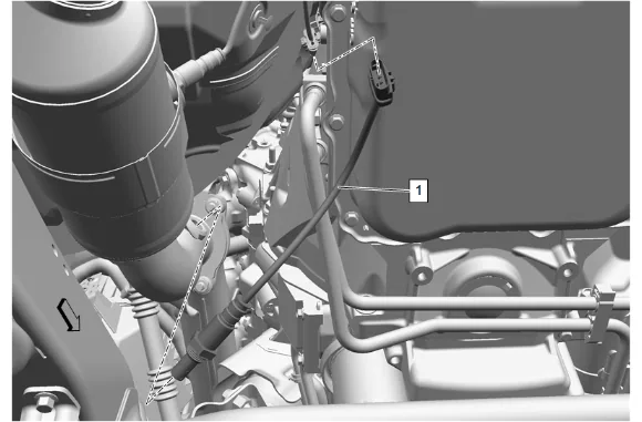
- Disconnect the heated oxygen sensor electrical connector.
- Remove the heated oxygen sensor (1) using a suitable tool.
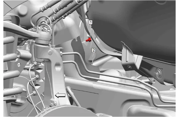
- Exhaust Heat Shield Bolt (1) » Remove
- Exhaust Front Pipe Heat Shield (2) » Remove
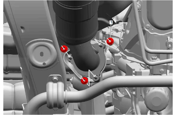
- Exhaust Front Pipe Nut - Left Side (1) » Remove [3x]
- Lower the vehicle.
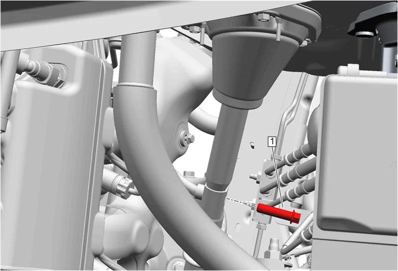
- Mid Intermediate Steering Shaft Bolt (1) » Remove
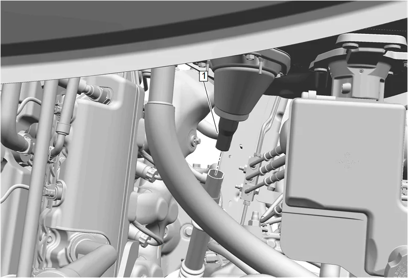
- Upper Intermediate Steering Shaft (1) @ Intermediate Steering Shaft » Separate
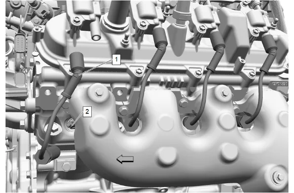
- Spark Plug Wire - Left Side (1) @ Gas Engine Ignition Spark Plug (2) » Remove and position aside [4x]
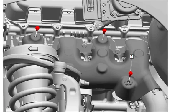
- Remove the 3 left side exhaust manifold heat shield bolts (1) through the wheel opening.
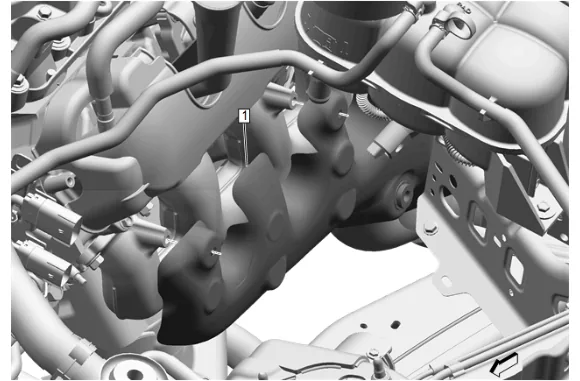
- Exhaust Manifold Heat Shield - Left Side (1) » Remove
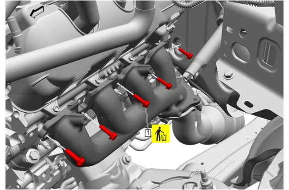
- Exhaust Manifold Bolt (1) » Remove and DISCARD [5x]
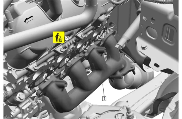
- Exhaust Manifold - Left Side (1) » Remove
- Exhaust Manifold Gasket (2) » Remove and DISCARD
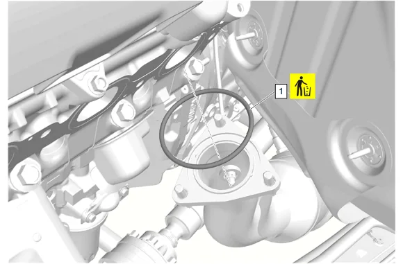
- Exhaust System Seal (1) » Remove and DISCARD
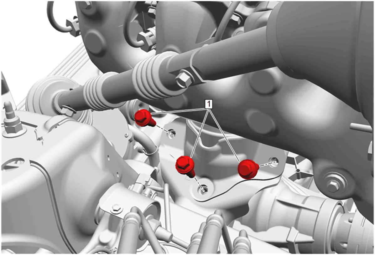
- Engine Mount Frame Side Bolt - Left Side (1) » Remove [3x]
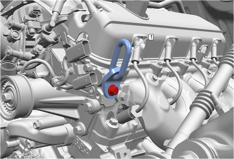
- Install the EN-36857 Engine Lift Bracket (1) to the front of the left side cylinder head as shown using the EN-52059 Engine Support Fixture Adaptor Bolt - M10.
- Raise the engine using a suitable lifting device to remove the engine mount.
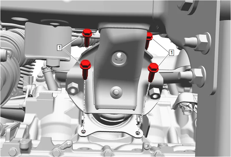
- Engine Mount Engine Side Bolt - Left Side (1) » Remove [4x]
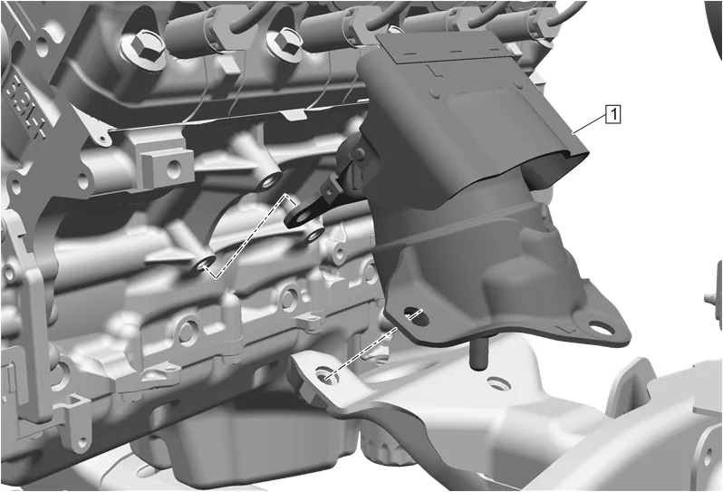
- Engine Mount - Left Side (1) » Remove Cleaning and Inspection Procedure - Conditional
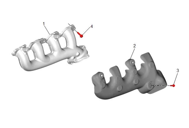
- Clean the exhaust manifold (1) and heat shield (2) in solvent.
- Dry the exhaust manifold (1) with compressed air.
- Inspect the exhaust manifold (1) to the cylinder head exhaust manifold gasket surface for excessive scratches or gouging.
- Inspect for a loose, damaged, or cracked heat shield (2).
- Inspect the heat shield bolts (3) for damaged threads.
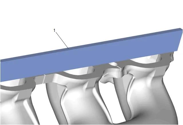
- Use a straight edge (1) and a feeler gauge and measure the exhaust manifold cylinder head deck for warpage. An exhaust manifold cylinder head deck with warpage in excess of 0.25 mm (0.01 in) within the 2 front or 2 rear runners or 0.5 mm (0.02 in) overall, may cause an exhaust leak. Exhaust manifolds not within specifications MUST be replaced.
-
Inspection the spark plug wire for the following conditions: 7.1. Correct routing of the spark plug wires. Incorrect routing may cause cross-firing. 7.2. Inspect for any signs of cracks or splits in the wires.
-
Inspect each boot for the following conditions: 8.1. Tearing 8.2. Piercing 8.3. Arcing 8.4. Carbon tracking 8.5. Corroded terminals
-
If corrosion, carbon tracking or arcing are indicated on a spark plug wire boot or on a terminal, replace the wire and the component connected to the wire. Installation Procedure
-
Engine Mount - Left Side (1) » Install
-
Prepare the 4 engine mount engine side bolts for installation as follows: 2.1. Remove any loose cured adhesive from the external threads of the components using a lint free cloth. 2.2. Thread the cleaned components into the internal mating threads and remove to loosen trapped cured adhesive. 2.3. Apply thread locking adhesive to the external threads of the components. Adhesives, Fluids, Lubricants, and Sealers 2.4. Ensure there are no gaps in the thread locking adhesive once applied to the component.
-
Engine Mount Engine Side Bolt - Left Side (1) » Install and hand tighten [4x]
-
Engine Mount Engine Side Bolt - Left Side (1) » Tighten [4x] — Fastener Specifications
-
Lower the engine.
-
Prepare the 3 engine mount frame side bolts for installation as follows: 6.1. Remove any loose cured adhesive from the external threads of the component using a lint free cloth. 6.2. Thread the cleaned component into the internal mating threads and remove to loosen trapped cured adhesive. 6.3. Apply thread locking adhesive to the external threads of the component. Adhesives, Fluids, Lubricants, and Sealers 6.4. Ensure there are no gaps in the thread locking adhesive once applied to the component.
-
Engine Mount Frame Side Bolt - Left Side (1) » Install and hand tighten [3x]
-
Engine Mount Frame Side Bolt - Left Side (1) » Tighten in sequence [3x] — Fastener Specifications
-
Remove the EN-52059 Engine Support Fixture Adaptor Bolt - M10 and EN-36857 Engine Lift Bracket (1) from the front of the left side cylinder head.
-
Exhaust System Seal (1) » Install NEW
-
Exhaust Manifold Gasket (2) » Install NEW
-
Exhaust Manifold - Left Side (1) » Install
-
If NEW threaded components are being installed, loosen the adhesive using a metal pick or similar tool before proceeding. If threaded components are reused, prepare the threaded components using the following steps: 13.1. Remove any loose cured adhesive from the external threads of the components using a lint free cloth. 13.2. Thread the cleaned components into the internal mating threads and remove to loosen trapped cured adhesive. 13.3. Apply thread locking adhesive to the external threads of the components. Adhesives, Fluids, Lubricants, and Sealers 13.4. Ensure there are no gaps in the thread locking adhesive once applied to the component.
-
Exhaust Manifold Bolt (1) » Install NEW and tighten in sequence [5x] — Fastener Specifications
-
Exhaust Manifold Heat Shield - Left Side (1) » Install
-
Through the wheel opening, install and tighten the 3 left side exhaust manifold heat shield bolts (1). Fastener Specifications
-
Inspect the inside of the 4 spark plug rubber boots for a thin, even coat of grease. If there is no grease present or additional grease is necessary, apply a thin coating of dielectric grease evenly to the inside of the 4 spark plug rubber boots up to a depth of 15 mm (0.59 in) from the end of the boots. Adhesives, Fluids, Lubricants, and Sealers.
-
Push the boot of the 4 spark plug wires (1) onto the 4 gas engine ignition spark plugs (2) until 2 audible clicks are heard.
-
Upper Intermediate Steering Shaft (1) @ Intermediate Steering Shaft » Install
-
If a NEW threaded component is being installed, loosen the adhesive using a metal pick or similar tool before proceeding. If threaded component is reused, prepare the threaded component using the following steps: 20.1. Remove any loose cured adhesive from the external threads of the component using a lint free cloth. 20.2. Thread the cleaned component into the internal mating threads and remove to loosen trapped cured adhesive. 20.3. Apply thread locking adhesive to the external threads of the component. Adhesives, Fluids, Lubricants, and Sealers 20.4. Ensure there are no gaps in the thread locking adhesive once applied to the component.
-
Mid Intermediate Steering Shaft Bolt (1) » Install and tighten — Fastener Specifications
-
Exhaust Front Pipe Nut - Left Side (1) » Install and tighten [3x] — Fastener Specifications
-
Exhaust Front Pipe Heat Shield (2) » Install
-
Exhaust Heat Shield Bolt (1) » Install and tighten — Fastener Specifications
- Install and tighten the heated oxygen sensor (1) using a suitable tool. Fastener Specifications
- Connect the heated oxygen sensor electrical connector.
- Front Wheelhouse Liner » Install — Front Wheelhouse Liner Replacement
- Lower the vehicle.
- Connect the battery negative cable. Battery Negative Cable Disconnection and Connection
- Start the engine and check for exhaust leaks.