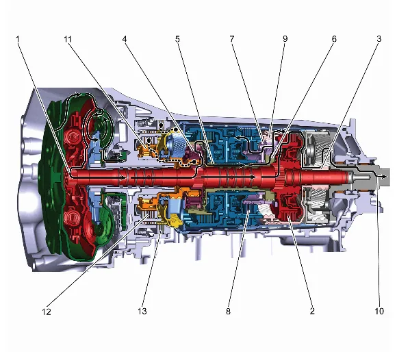
Drive Range, First Gear (Mechanical Powerflow)
- Power from Torque Converter The power flows through the turbine shaft to the 1-3-5-6-7-8-9 clutch assembly (554-565).
- 1-3-5-6-7-8-9 Clutch Assembly Applied The 1-3-5-6-7-8-9 clutch assembly (554-565) is applied and holds the output sun gear (572).
- Output Sun Gear Driving The output sun gear (572) is driving the output carrier (38) pinion gears.
- Input Carrier Driving The power flows to the input carrier (62) which is splined to the turbine shaft (568) and rotates at the same speed and direction. Power flow continues through the input carrier pinion gears which are driving the direct overdrive sun gear shaft (65).
- Direct Overdrive Sun Gear Shaft Driven The input internal gear (500) which is splined to the direct overdrive sun gear shaft (65) and rotates at the same speed and direction is driven by the input carrier (62) pinion gears.
- Direct Overdrive Sun Gear Driving The direct overdrive sun gear (68) which is splined to the direct overdrive sun gear shaft (65) is driving the direct overdrive carrier (67) pinion gears.
- Direct Overdrive Carrier Driven The direct overdrive carrier (67) is driven by the direct overdrive sun gear (68).
- 1-2-3-4-6-7-8-10 Reverse Clutch Assembly Applied The 1-2-3-4-6-7-8-10 reverse clutch is applied, but not with line pressure. It only has enough pressure to prevent the 1-2-3-4-6-7-8-10 Reverse Clutch from slip. The 1-2-3-4-6-7-8-10 reverse clutch which is part of the triple clutch housing (66) is applied and holding the direct overdrive carrier (67) which is driven by the direct overdrive sun gear (68).
- Direct Overdrive Internal Gear Driven The direct overdrive internal gear (551) which is splined to the output sun gear (572) is driven by the direct overdrive carrier (67) pinion gears.
- Output Carrier Driven Powerflow continues through the output sun gear (572). Which drives the output carrier (38) pinions to achieve the 1st gear starting ratio of approximately 4.696:1.
- Low Clutch Roller Holding The power transferred to the input carrier (62) by the output carrier pinion gears attempts to rotate the carrier. The carrier is held stationary by the low clutch roller (421), and the low clutch roller is held stationary by the 1-2-8-9-10 reverse clutch assembly (414-420) being applied hydraulically during engine braking.
- 1-2-8-9-10 Reverse Clutch Assembly Applied The 1-2-8-9-10 reverse clutch assembly (414-420) is applied and holding the low clutch roller (421) which is splined to the reaction sun gear (572) and held stationary.
- 1-2-3-4-5-6 Reverse Clutch Assembly Applied The 1-2-3-4-5-6 reverse clutch assembly (30-35) is applied and holding the reaction internal gear (52) which is held stationary. Drive Range First Gear