Transfer Case Assemble
Single Use Fasteners and Components Transfer Case Access Hole Plug Transfer Case Four Wheel Drive Clutch Housing Retaining Ring Transfer Case Front Output Shaft Boot Transfer Case Front Output Shaft Boot Clamp Transfer Case Front Output Shaft Drive Sprocket Retaining Ring Transfer Case Input Shaft Bearing Outer Retaining Ring Transfer Case Input Shaft Bearing Retaining Ring Transfer Case Rear Output Shaft Rear Bearing Retaining Ring Transfer Case Rear Output Shaft Seal Transfer Case Two/Four Wheel Drive Actuator Position Sensor Gasket Transfer Case Two/Four Wheel Drive Clutch Retaining Ring Transfer Case Vent Special Tools DT-42738 Seal Installer DT-45759 Assembly Fixture DT-48213 Clutch Pack Height Gauge DT-50648–A Seal Installer DT-51204 Case Separating Tool J-44636-1 Front Output Shaft Seal Protector J-44636-2 Front Output Shaft Seal Installer GE-3289-20 Holding Fixture Equivalent regional tools: Special Tools
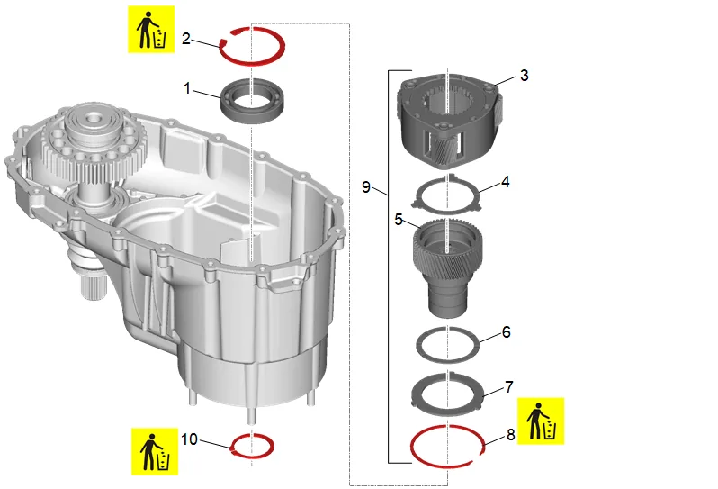
- Transfer Case Input Shaft Bearing (1) » Install
- Transfer Case Input Shaft Bearing Outer Retaining Ring (2) » Install NEW
- Transfer Case High/Low Planetary Carrier (3) » Install
- Transfer Case High/Low Planetary Carrier Pinion Gear Thrust Washer (4) » Install
- Transfer Case Input Shaft (5) » Install
- Transfer Case High/Low Planetary Carrier Pinion Gear Thrust Washer (6) » Install
- Transfer Case High/Low Locking Plate (7) » Install NEW
- Transfer Case Input Shaft Bearing Retaining Ring (8) » Install
- Transfer Case Input Shaft/Planetary Assembly (9) » Install
- Transfer Case Input Shaft Bearing Outer Retaining Ring (10) » Install NEW
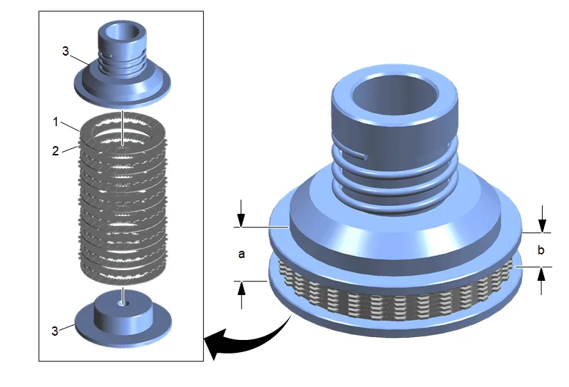
- The DT-48213 Clutch Pack Height Gauge (3) applies a predetermined amount of pressure to the clutch pack in order to properly measure the clutch pack height. Do not use any other method than what is outlined below.
- Micrometers or depth gauges may also be used in conjunction with the DT-48213 Clutch Pack Height Gauge (3) to measure the clutch pack height.
- Two variations are available to measure clutch pack height, outside measurement or inside measurement. Either variation will determine the correct height.
- Transfer Case Four Wheel Drive Clutch Pressure Plate – Friction(1) » Install [8x] 14.1. Install the friction and steel clutch plates into the DT-48213 Clutch Pack Height Gauge (3), alternating until 8 friction plates and 7 steel plates are installed.
- Transfer Case Four Wheel Drive Clutch Pressure Plate – Steel (1) » Install [7x] 15.1. Tighten the DT-48213 Clutch Pack Height Gauge (3) until the upper portion of the tool contacts the lower portion of the tool. The screw will be flush with the bottom surface of the tool to indicate the tool has fully compressed the clutch plates. 15.2. Using an outside caliper, measure the total combined height of the clutch pack and the DT- 48213 Clutch Pack Height Gauge (3), dimension (a). Subtract the thickness of both the upper and lower portion of the DT-48213 Clutch Pack Height Gauge (3), 14 mm (0.551 in), and record the results. 15.3. Repeat the process in 2 additional locations, 120 degrees from each other. 15.4. The average of the 3 measurements is the clutch pack height. 15.5. Install the friction and steel clutch plates into the DT-48213 Clutch Pack Height Gauge (3), alternating until 8 friction plates and 7 steel plates are installed. 15.6. Tighten the DT-48213 Clutch Pack Height Gauge (3) until the upper portion of the tool contacts the lower portion of the tool. The screw will be flush with the bottom surface of the tool to indicate the tool has fully compressed the clutch plates. 15.7. Using an inside caliper, measure the height of the clutch pack, dimension (b), and record the results. 15.8. Repeat the process in 2 additional locations, 120 degrees from each other. 15.9. The average of the 3 measurements is the clutch pack height.
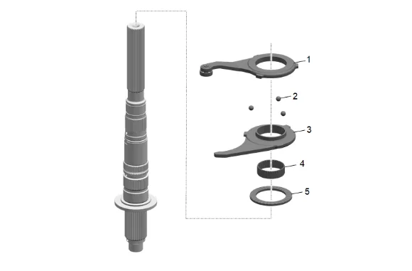
- Transfer Case Control Actuator Thrust Bearing (5) » Install
- Transfer Case Control Actuator Lever Bearing Assembly (4) » Install
- Transfer Case Scissor Mechanism Lever (3) » Install
- Transfer Case Scissor Lever Ball (2) » Install [3x]
- Transfer Case Scissor Mechanism Lever (1) » Install
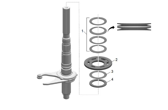
- Transfer Case Control Actuator Lever Bearing (4) » Install
- Transfer Case Control Actuator Lever Washer (3) » Install
- Transfer Case Four Wheel Drive Clutch Pressure Plate – Apply(2) » Install
- Transfer Case Four Wheel Drive Clutch Pressure Plate Spring (1) » Install [4x]
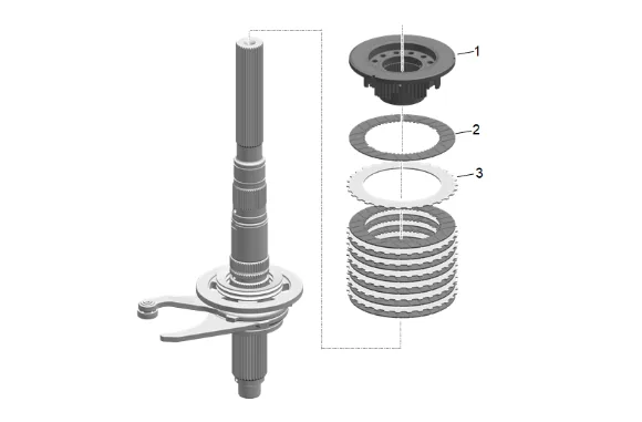
- Transfer Case Four Wheel Drive Clutch Pressure Plate – Friction (2) » Install [8x]
- Transfer Case Four Wheel Drive Clutch Pressure Plate – Steel (3) » Install [7x]
- Transfer Case Four Wheel Drive Clutch Hub (1) » Install
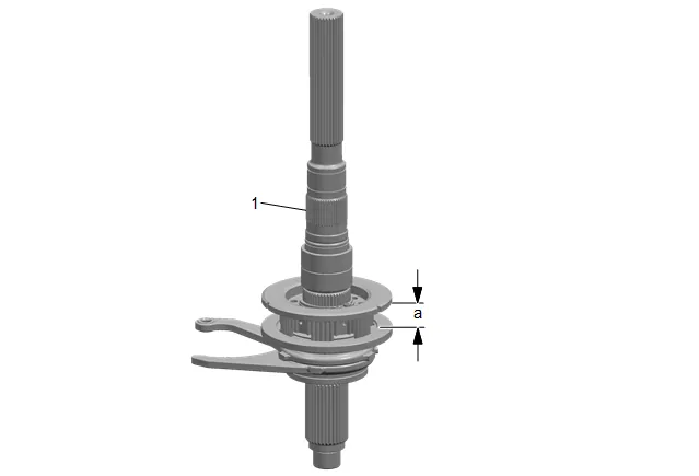
- Using an inside caliper, measure the height of the clutch assembly in the location (a) shown and record the results.
- Repeat the process in 2 additional locations, 120 degrees from each other.
- The average of the 3 measurements is the clutch assembly height.
- A 3.1 mm (0.122 in) clearance +/− 0.1 mm (0.004 in) is necessary between the clutch pack height and the assembly height. It may be necessary to replace the clutch shim with a thicker shim or a thinner shim, to achieve the proper clearance in the clutch.
- Subtract the clutch pack height from the clutch assembly height. The difference should be between 3.0 mm (0.118 in) and 3.2 mm (0.126 in) clearance.
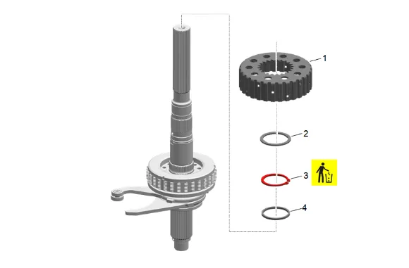
- Transfer Case Four Wheel Drive Clutch Shim (4) » Install
- Transfer Case Two/Four Wheel Drive Clutch Retaining Ring (3) » Install NEW
- Transfer Case Front Output Shaft Driven Sprocket Spacer - Front (2) » Install
- Transfer Case Four Wheel Drive Clutch Housing (1) » Install
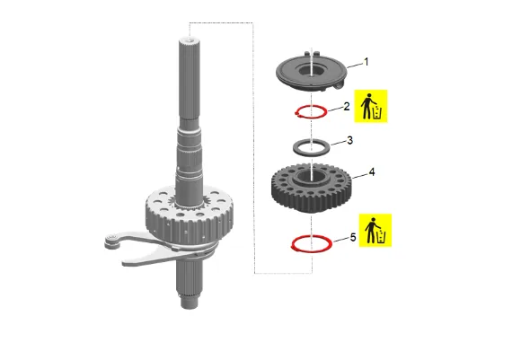
- Transfer Case Four Wheel Drive Clutch Housing Retaining Ring (5) » Install NEW
- Transfer Case Front Output Shaft Drive Sprocket (4) » Install
- Transfer Case Front Output Shaft Driven Sprocket Spacer - Rear (3) » Install
- Transfer Case Front Output Shaft Drive Sprocket Retaining Ring (2) » Install
- Transfer Case Oil Pump (1) » Install
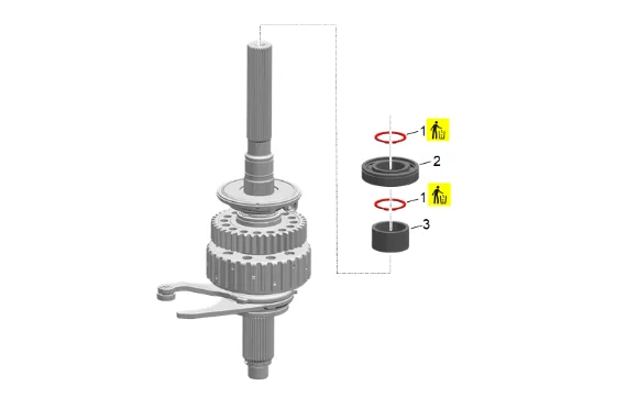
- Transfer Case Rear Output Shaft Bearing Spacer (3) » Install
- Transfer Case Rear Output Shaft Rear Bearing Retaining Ring (1) » Install NEW
- Transfer Case Rear Output Shaft Rear Bearing (2) » Install 44.1. Use an arbor press or suitable installer to install the bearing to the rear output shaft. 44.2. Ensure the retaining ring groove in the outer race is positioned toward the rear.
- Transfer Case Rear Output Shaft Rear Bearing Retaining Ring (1) » Install NEW
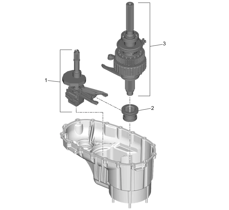
- Transfer Case High/Low Shift Fork Assembly (1) » Install
- Transfer Case High/Low Clutch (2) » Install
- Transfer Case Rear Output Shaft Assembly (3) » Install
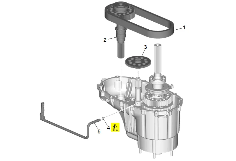
- Transfer Case Front Output Shaft Drive Chain Assembly (1) » Install 49.1. Install the chain with darkened links up. 49.2. Install the front output shaft assembly into the front case half while engaging the chain with the drive sprocket.
- Transfer Case Front Output Shaft (2) » Install
- Install the transfer case actuator shaft gear (3).
- Transfer Case Oil Pump Suction Pipe Seal (4) » Install NEW 52.1. Lubricate the seal to ease installation. 52.2. Install the seal to the pipe prior to inserting the pipe into the pump.
- Transfer Case Oil Pump Suction Pipe (5) » Install
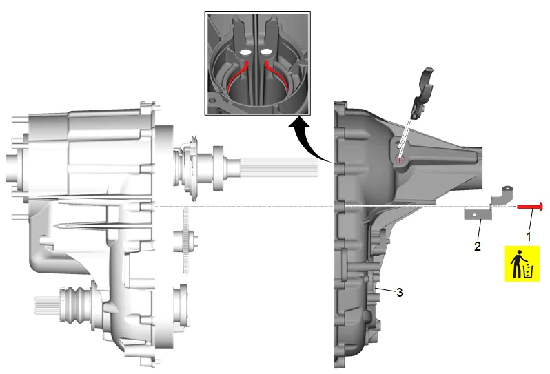
- Transfer Case Front Case Half (1) » Install
- Transfer Case Rear Case Half (2) » Install 55.1. Ensure the transfer case rear output shaft outer retaining ring is in place and aligned prior to mating case halves. 55.2. Use snap ring pliers to open the transfer case rear output shaft outer retaining ring for the transfer case rear output shaft rear bearing assembly. 55.3. Ensure snap ring is sitting properly by rotating the entire transfer case and then let gravity seat the snap ring. Listen for a definite click sound.
- Transfer Case Bracket (3) » » Install
- Transfer Case Half Bolt (4) » Install NEW and tighten [17x] — Fastener Specifications
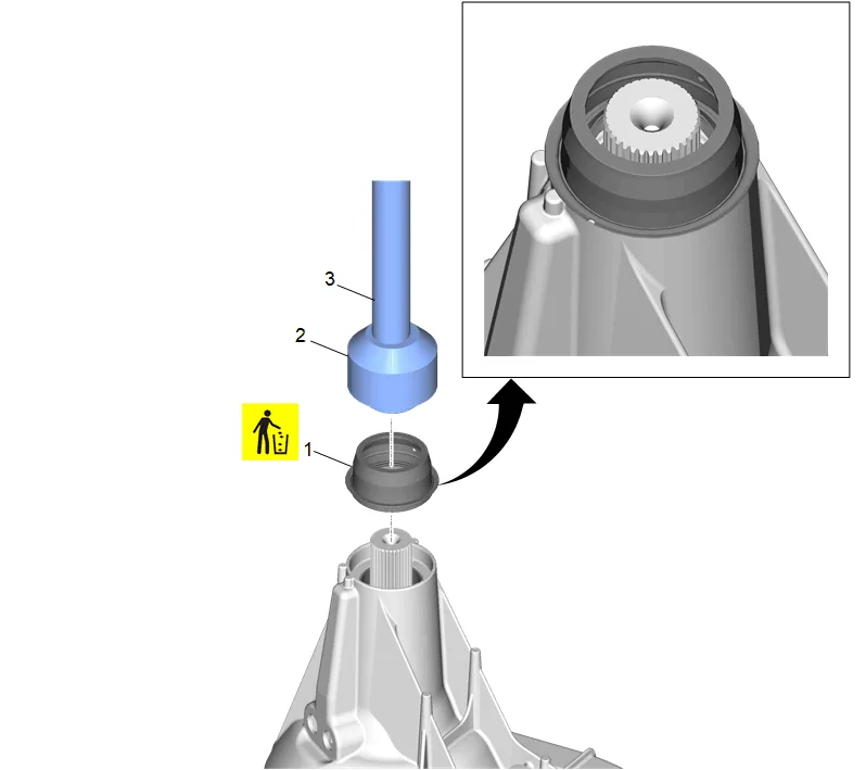
- Using the DT-48210 Seal Installer (2) and J-8092 Driver Handle (3) install a NEW transfer case rear output shaft seal (1).
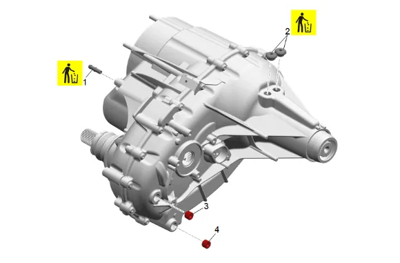
- Transfer Case Vent (1) » Install NEW
- Transfer Case Access Hole Plug (2) » Install NEW [2x]
- Transfer Case Oil Fill Plug (3) » Install — Fastener Specifications
- Transfer Case Oil Drain Plug (4) » Install — Fastener Specifications
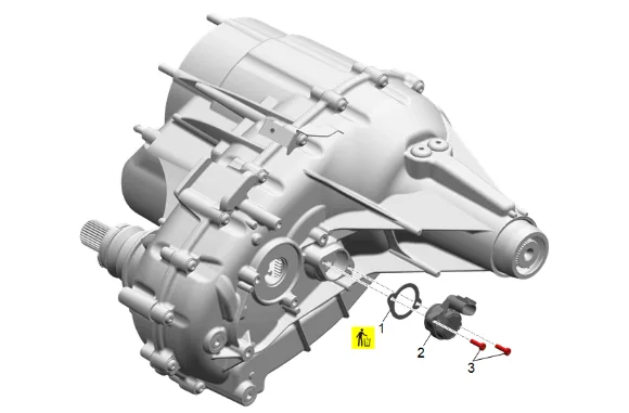
- Transfer Case Two/Four Wheel Drive Actuator Position Sensor Gasket (1) » Install NEW
- Transfer Case Two/Four Wheel Drive Actuator Position Sensor (2) » Install
- Transfer Case Two/Four Wheel Drive Actuator Position Sensor Bolt (3) » Install [2x] — Fastener Specifications
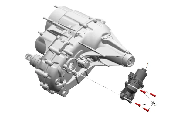
- Transfer Case Two/Four Wheel Drive Actuator (1) » Install
- Transfer Case Two/Four Wheel Drive Actuator Bolt/Screw (2) » Install and tighten [4x] — Fastener Specifications
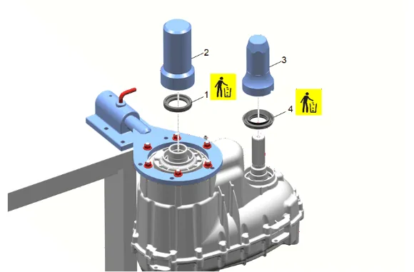
- Install a NEW transfer case input shaft seal (1) using the DT-42738 Seal Installer (2).
- Install a NEW transfer case front output shaft seal (4) using the DT-50648–A Seal Installer (3)
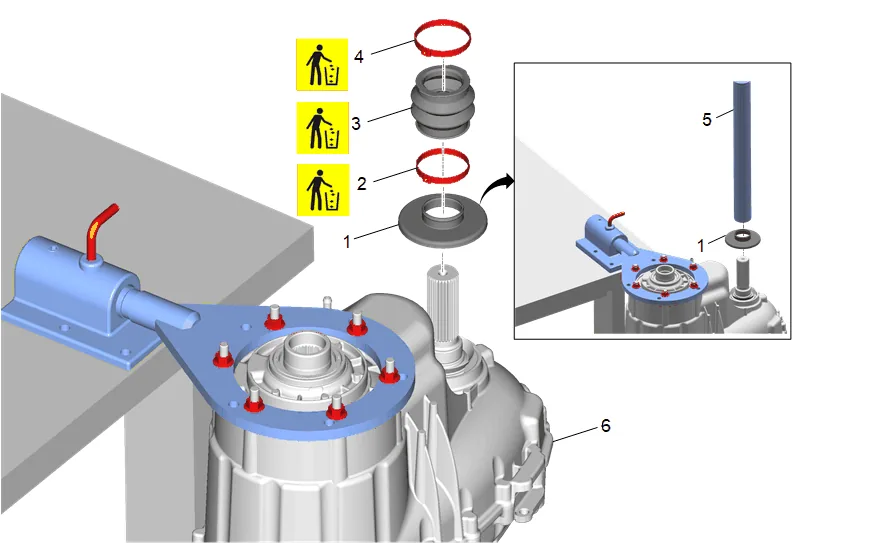
- Use J-44636-2 Front Output Shaft Seal Installer (5) to install the transfer case front output shaft oil slinger (1).
- Transfer Case Front Output Shaft Boot Clamp (2) » Install NEW
- Transfer Case Front Output Shaft Boot (3) » Install NEW
- Transfer Case Front Output Shaft Boot Clamp (2) » Install NEW
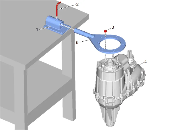
- Transfer Case Nut (3) » Remove [6x]
- Remove the transfer case (4) from the GE-3289-20 Holding Fixture (1) and DT-45759 Assembly Fixture (5).