Tire and Wheel Balancing
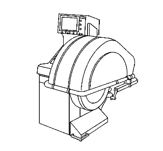
- Spin the balancer without a wheel or any of the adapters on the shaft.
- Inspect the balancer readings. Specification SpecificationZero within 7 g (¼ oz)
- If the balancer is within the specification range, balance a tire and wheel assembly - that is within radial and lateral runout tolerances - to ZERO, using the same balancer.
- After the tire and wheel assembly has been balanced, add an 85 g (3 oz) test weight to the wheel at any location.
- Spin the tire and wheel assembly again. Note the readings. In the static and dynamic modes, the balancer should call for 85 g (3 oz) of weight, 180 degrees opposite the test weight. In the dynamic mode, the weight should be called for on the flange of the wheel opposite the test weight.
- With the assembly imbalanced to 85 g (3 oz), cycle the balancer 5 times.
- Inspect the balancer readings: Specification SpecificationMaximum variation: 7 g (¼ oz)
- Index the tire and wheel assembly on the balancer shaft, 90 degrees from the previous location.
- Cycle the balancer with the assembly at the new location.
- Inspect the balancer readings: Specification SpecificationMaximum variation: 7 g (¼ oz)
- Repeat steps 8 through 10 until the tire and wheel assembly has been cycled and checked at each of the 4 locations on the balancer shaft. Tire and Wheel Assembly Balancing Guidelines
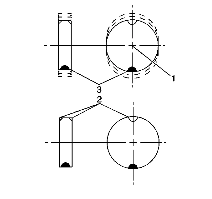
Static balance is the equal distribution of weight around the wheel circumference. The wheel balance weights (2) are positioned on the wheel in order to offset the effects of a heavy spot (3). Wheels that have static imbalance can produce a bouncing action called tramp. Dynamic Balance
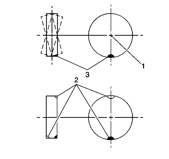
Dynamic balance is the equal distribution of weight on each side of the tire and wheel assembly centerline. The wheel balance weights (2) are positioned on the wheel in order to offset the effects of a heavy spot (3). Wheels that have dynamic imbalance have a tendency to move from side to side and can cause an action called shimmy. Most off-vehicle balancers are capable of checking both types of balance simultaneously. As a general rule, most vehicles are more sensitive to static imbalance than to dynamic imbalance. However, vehicles equipped with low profile, wide tread path, high performance tires and wheels are susceptible to small amounts of dynamic imbalance. As little as 14-21 g (½-¾ oz) imbalance is capable of inducing a vibration in some vehicle models. Balancing Procedure
- Raise and support the vehicle. Lifting and Jacking the Vehicle
- Mark the location of the wheels to the wheel studs and mark the specific vehicle position on each tire and wheel - LF, LR, RF, RR.
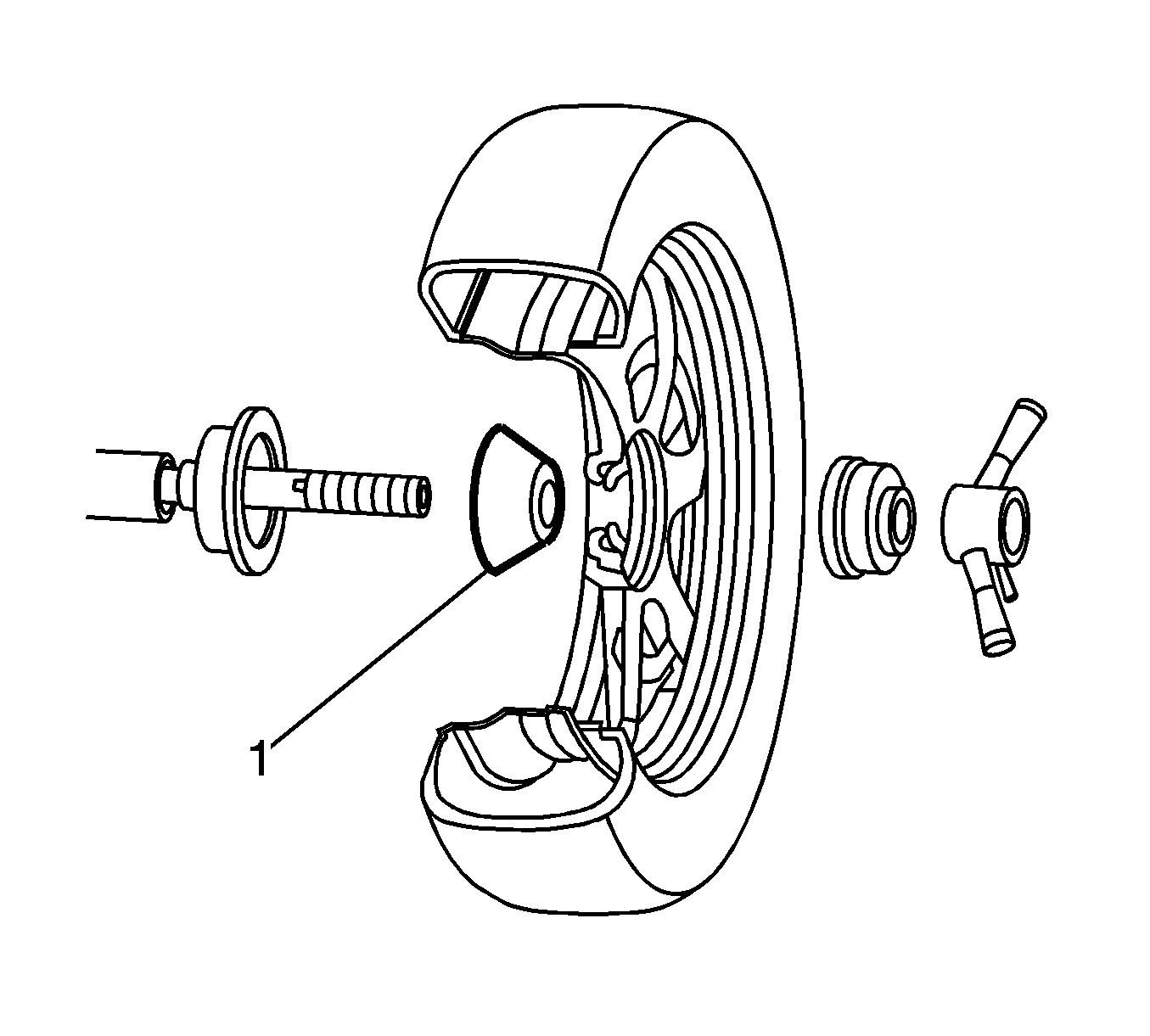
- Remove the tire and wheel assemblies one at a time and mount on a spin-type wheel balancer. Tire and Wheel Removal and Installation
- Carefully follow the wheel balancer manufacturer’s instructions for proper mounting techniques to be used on different types of wheels. Regard aftermarket wheels, especially those incorporating universal lug patterns, as potential sources of runout and mounting concerns.
- Be sure to use the correct type of wheel balance weights for the type of wheel rim being balanced. Be sure to use the correct type of coated wheel balance weights on aluminum wheels. Refer to Wheel Weight Usage section below.
- Balance all four tire and wheel assemblies as close to zero as possible.
- Using the matchmarks made prior to removal, install the tire and wheel assemblies to the vehicle. Tire and Wheel Removal and Installation
- Lower the vehicle. Wheel Weight Usage Tire and wheel assemblies can be balanced using either the static or dynamic method. Clip-on Weights
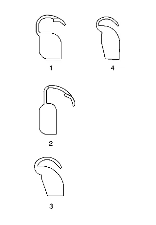
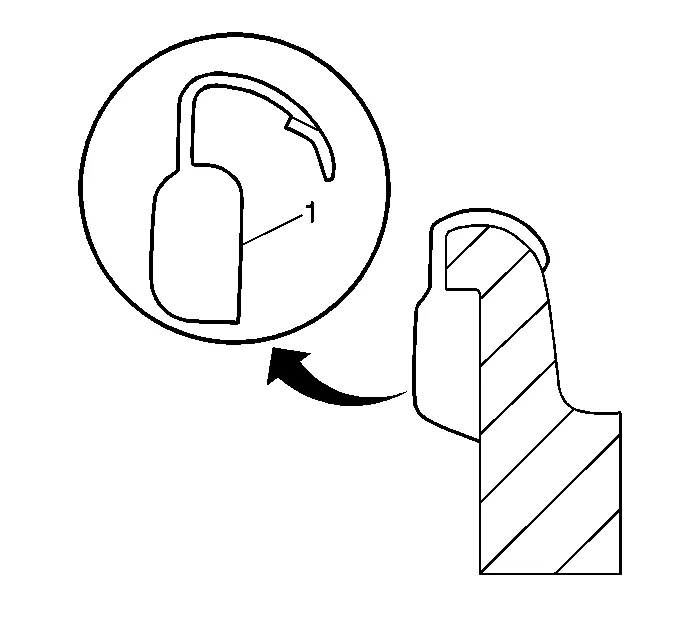
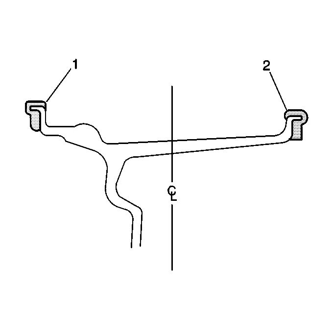
When static balancing, locate the wheel balance weights on the inboard flange (2) if only 28 g (1 oz) or less is called for. If more than 28 g (1 oz) is called for, split the weights as equally as possible between the inboard (2) and outboard (1) flanges. When dynamic balancing, locate the wheel balance weights on the inboard (2) and outboard (1) rim flanges at the positions specified by the wheel balancer. Adhesive Weights
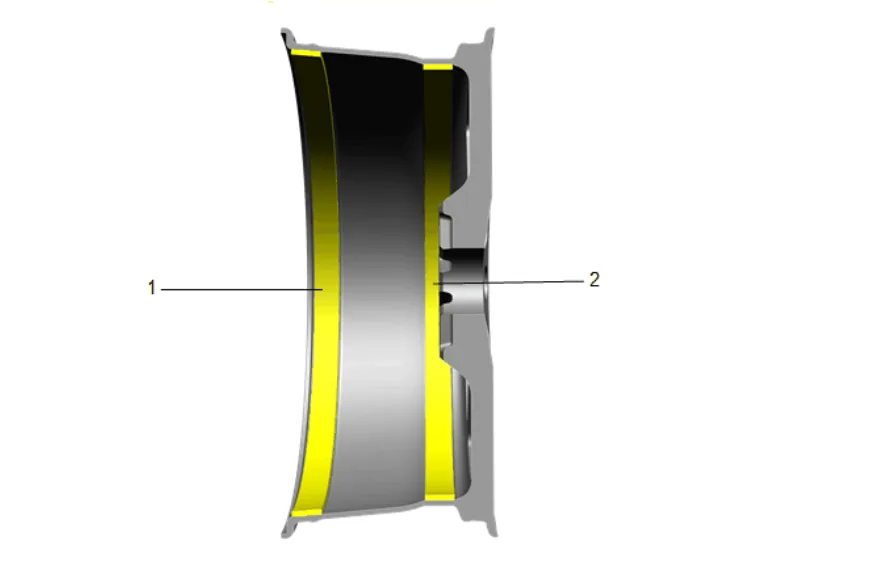
- Determine the correct areas for placement of the wheel weights on the wheel. Wheels are designed with features such as recesses or flat surfaces to house the adhesive wheel weights typically at the most inboard (1) and outboard (2) surfaces. These position features limit any interference installed adhesive weights could have with adjacent components during normal vehicle operation.
- Ensure that there is sufficient clearance between the wheel weights and brake system components.
- Using a clean cloth or paper towel with a general purpose cleaner, thoroughly clean the designated balance weight attachment areas of any corrosion, overspray, dirt or any other foreign material.
- To ensure there is no remaining residue, wipe the balance weight attachment areas again, using a clean cloth or paper towel with a mixture of half isopropyl alcohol and half water.
- Dry the attachment areas with hot air until the wheel surface is warm to the touch.
- Warm the adhesive backing on the wheel balance weights to room temperature.
- Remove the protective covering from the adhesive backing on the back of the balance weights. DO NOT touch the adhesive surface.
- Apply the wheel balance weights to the wheel, press into place with hand pressure.
- Secure the wheel balance weights to the wheel with a 90 N (21 lb) force applied with a roller.