Heater and Air Conditioning User Interface Control Replacement (without DCH, D07)
Heater and Air Conditioning User Interface Control Replacement (without DCH, D07) Removal Procedure
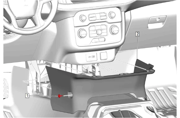
- Instrument Panel Lower Trim Panel Bolt (1) » Remove
- Using a flat-bladed plastic trim tool, release the retaining clips.
- Instrument Panel Lower Center Trim Panel (2) » Remove
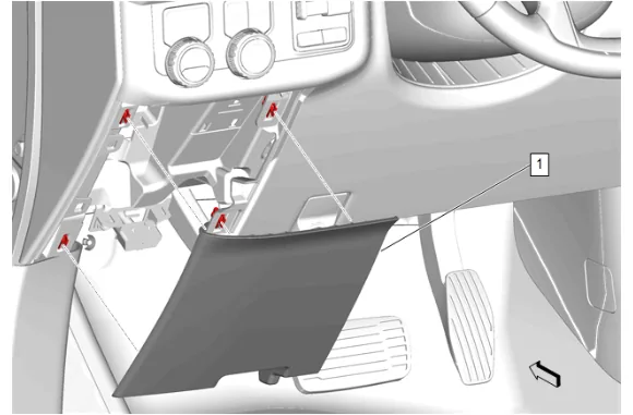
- Instrument Panel Lower Trim Panel Outer Filler (1) » Remove
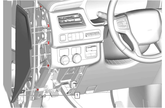
- Using a flat-bladed plastic trim tool, release the retaining clips.
- Instrument Panel Fuse Block Access Hole Cover (1) » Remove
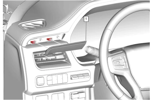
- Using a flat-bladed plastic trim tool, release the retaining clips.
- Instrument Panel Trim Plate Applique (1) » Remove
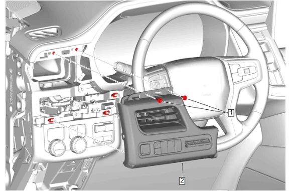
- Instrument Panel Trim Pad Bolt (1) » Remove [2x]
- Disconnect the electrical connectors.
- Instrument Panel Trim Pad (2) » Remove
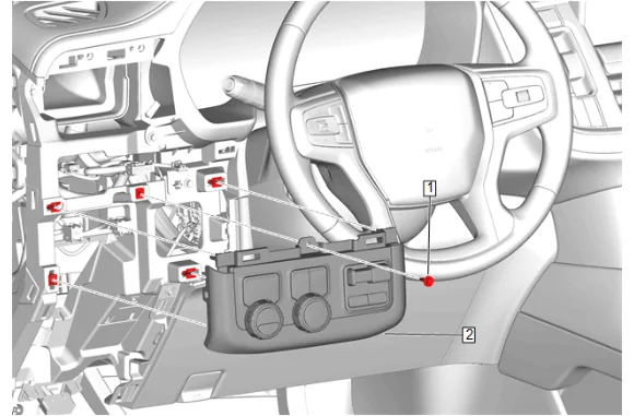
- Instrument Panel Switch Trim Plate Bolt (1) » Remove
- Disconnect the electrical connectors.
- Instrument Panel Switch Trim Plate (2) » Remove
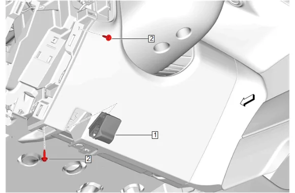
- Hood Primary Latch Release Cable Handle (1) » Release
- Instrument Panel Knee Bolster Bolt (2) » Remove [2x]
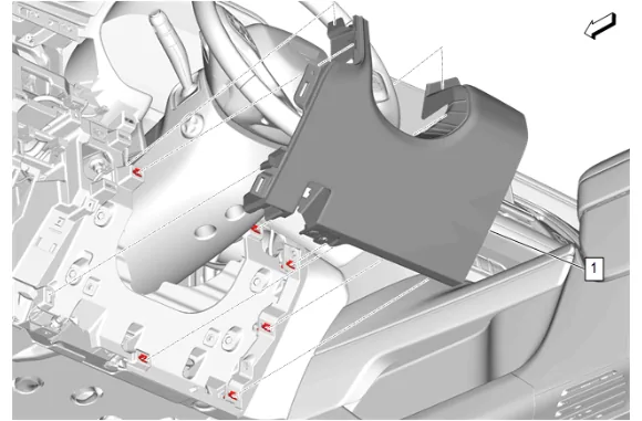
- Instrument Panel Knee Bolster (1) » Remove
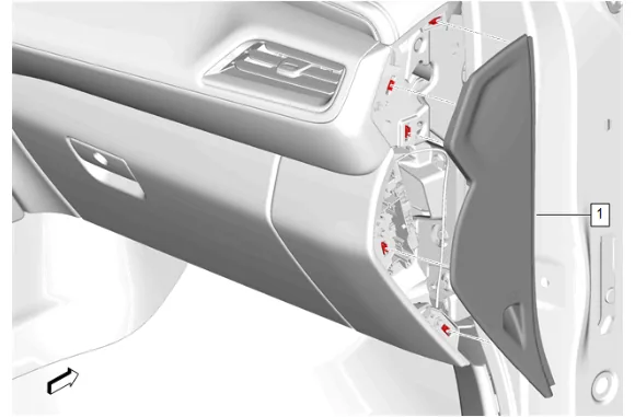
- Using a flat-bladed plastic trim tool, release the retaining clips.
- Instrument Panel Fuse Block Access Hole Cover (1) » Remove
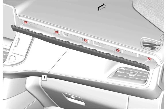
- Using a flat-bladed plastic trim tool, release the retaining clips.
- Instrument Panel Trim Plate Applique (1) » Remove
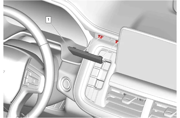
- Using a flat-bladed plastic trim tool, release the retaining clips.
- Instrument Panel Center Trim Plate Applique (1) » Remove
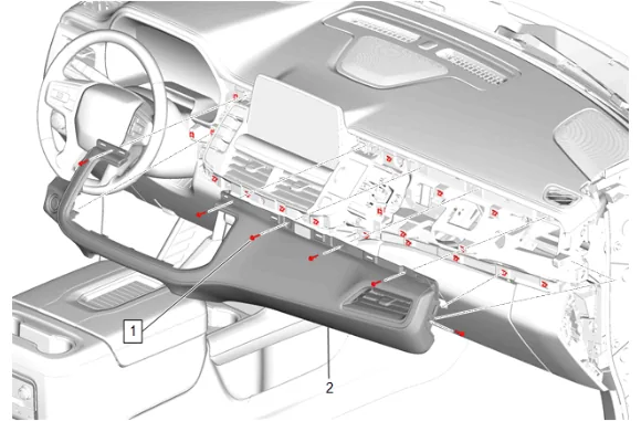
- Instrument Panel Upper Trim Panel Bolt (1) » Remove [6x]
- Using a flat-bladed plastic trim tool, release the retaining clips.
- Disconnect the electrical connector.
- Instrument Panel Trim Pad (2) » Remove
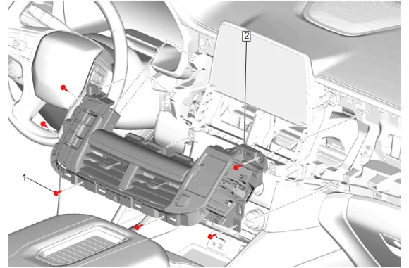
- Instrument Panel Center Trim Panel Bolt (1) » Remove [6x]
- Disconnect the electrical connectors.
- Instrument Panel Transmission Shift Opening Cover (2) » Remove
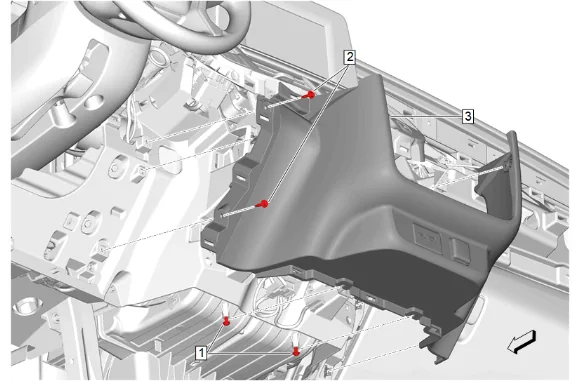
- Instrument Panel Lower Trim Panel Bolt (1) » Loosen [2x]
- Instrument Panel Lower Trim Panel Bolt (2) » Remove [2x]
- Instrument Panel Lower Trim Panel (3) » Remove
- Disconnect the electrical connectors.
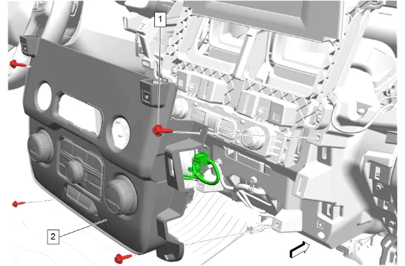
- Instrument Panel Accessory Bezel Bolt (1) » Remove [4x]
- Reposition the component to access the electrical connector.
- Disconnect the electrical connector.
- Instrument Panel Accessory Bezel (2) » Remove
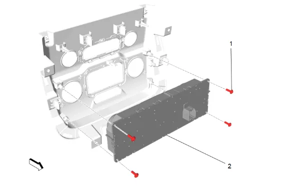
-
Heater and Air Conditioning User Interface Control Bolt (1) » Remove [4x]
-
Heater and Air Conditioning User Interface Control (2) » Remove Installation Procedure
-
Heater and Air Conditioning User Interface Control (2) » Install
-
Heater and Air Conditioning User Interface Control Bolt (1) » Install and tighten [4x] — Fastener Specifications
-
Connect the electrical connector.
-
Instrument Panel Accessory Bezel (2) » Install
-
Instrument Panel Accessory Bezel Bolt (1) » Install and tighten [4x] — Fastener Specifications
-
Connect the electrical connectors.
-
Instrument Panel Lower Trim Panel (3) » Install
-
Instrument Panel Lower Trim Panel Bolt (2) » Install and tighten [2x] — Fastener Specifications
-
Instrument Panel Lower Trim Panel Bolt (1) » Tighten [2x] — Fastener Specifications
-
Connect the electrical connectors.
-
Instrument Panel Transmission Shift Opening Cover (2) » Install
-
Instrument Panel Center Trim Panel Bolt (1) » Install and tighten [6x] — Fastener Specifications
-
Connect the electrical connector.
-
Instrument Panel Trim Pad (2) » Install
-
Instrument Panel Upper Trim Panel Bolt (1) » Install and tighten [6x] — Fastener Specifications
-
Instrument Panel Center Trim Plate Applique (1) » Install
-
Instrument Panel Trim Plate Applique (1) » Install
-
Instrument Panel Fuse Block Access Hole Cover (1) » Install
-
Instrument Panel Knee Bolster (1) » Install
-
Instrument Panel Knee Bolster Bolt (2) » Install and tighten [2x] — Fastener Specifications
-
Hood Primary Latch Release Cable Handle (1) » Install
-
Connect the electrical connectors.
-
Instrument Panel Switch Trim Plate (2) » Install
-
Instrument Panel Switch Trim Plate Bolt (1) » Install and tighten — Fastener Specifications
-
Connect the electrical connectors.
-
Instrument Panel Trim Pad (2) » Install
-
Instrument Panel Trim Pad Bolt (1) » Install and tighten [2x] — Fastener Specifications
-
Instrument Panel Trim Plate Applique (1) » Install
-
Instrument Panel Fuse Block Access Hole Cover (1) » Install
-
Instrument Panel Lower Trim Panel Outer Filler (1) » Install
-
Instrument Panel Lower Center Trim Panel (2) » Install
-
Instrument Panel Lower Trim Panel Bolt (1) » Install and tighten — Fastener Specifications