Front Differential Carrier Assembly Replacement (without F47)
Front Differential Carrier Assembly Replacement (without F47) Single Use Fasteners and Components Front Differential Carrier Bolt Front Differential Carrier Cover Gasket Front Differential Drive Pinion Gear Bearing Spacer Front Differential Drive Pinion Gear Nut Front Differential Drive Pinion Gear Seal Front Drive Axle Inner Shaft Retaining Ring Front Drive Axle Inner Shaft Seal Front Wheel Drive Shaft Nut [2x] Front Wheel Drive Shaft Retaining Ring [2x] Front Wheel Drive Shaft Seal [2x] Front Wheel Drive Shaft Slinger Special Tools Front Drive Axle DT-08614-20 Flange Retaining Bolts DT-22912-B Bearing Remover DT-24433 Pinion Cone and Side Bearing Installer DT-3289-20 Holding Fixture DT-35512 Inner Pinion Bearing Installer DT-38869 Rear Extension Seal Installer DT-45704 Pinion Bearing Race Installer - Dana 248 DT-52297 Front Axle Holding Fixture DT-52506 Pinion Flange Holder and Remover DT-52555 Side Bearing Installer DT-52556 Outer Pinion Bearing Cup Installer EN-45059-A Angle Meter EN-47966 Oil Control Valve Seal Remover GE-02619-A Slide Hammer w/Adapter GE-8092 Driver Handle Equivalent regional tools: Special Tools Front Suspension CH-42188-B Ball Joint Separator CH-43631 Ball Joint Separator Equivalent regional tools: Special Tools Wheel Drive Shafts DT-45859 Axle Remover Equivalent regional tools: Special Tools
- Disconnect the battery negative cable. Battery Negative Cable Disconnection and Connection
- Raise and support the vehicle. Lifting and Jacking the Vehicle
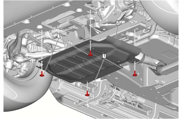
- {without RC1} Remove the underbody skid shield: 3.1. Underbody Skid Shield Bolt (1) » Remove [4x] 3.2. Underbody Skid Shield (2) » Remove
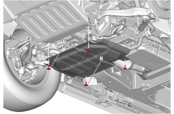
- {with RC1} Remove the underbody skid shield: 4.1. Underbody Skid Shield Bolt (1) » Remove [2x] 4.2. Underbody Splash Shield Bolt (2) » Remove [2x] 4.3. Underbody Skid Shield (3) » Remove
- Remove the front tire and wheel assemblies. Tire and Wheel Removal and Installation
- Have an assistant apply the brakes.
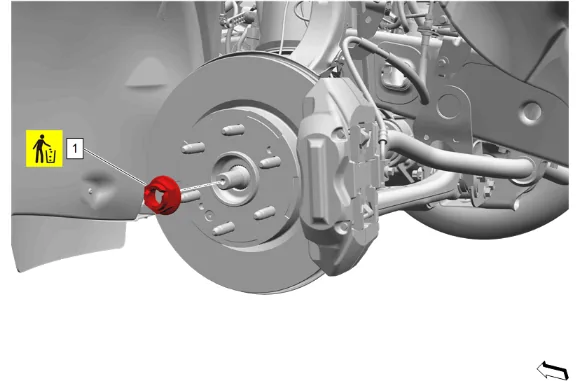
- Front Wheel Drive Shaft Nut (1) » Remove and DISCARD
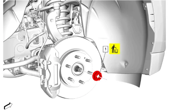
- Front Wheel Drive Shaft Nut (1) » Remove and DISCARD
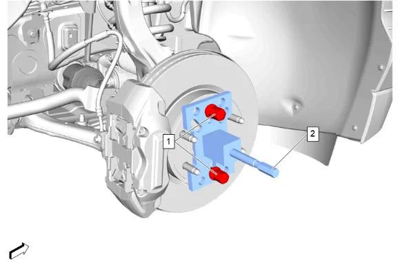
- Install the DT-45859 Axle Remover (2) to the front wheel hub and secure with 2 wheel nuts (1) hand tightened.
- Using the DT-45859 Axle Remover (2), release the front wheel drive half shaft from the front wheel hub.
- Remove the 2 wheel nuts (1) and the DT-45859 Axle Remover (2) from the front wheel hub.
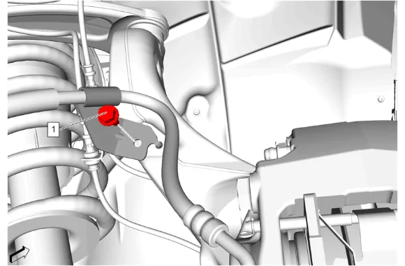
- Front Brake Hose Bracket Bolt (1) » Remove
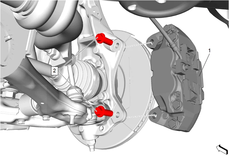
- Front Brake Caliper Bolt (2) » Remove [2x]
- Remove the brake caliper and support with heavy mechanics wire. (1)
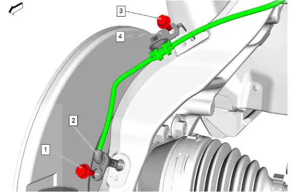
- Front Wheel Speed Sensor Bolt (1) » Remove
- Front Wheel Speed Sensor (2) » Remove
- Front Wheel Speed Sensor Bracket Bolt (3) » Remove
- Front Wheel Speed Sensor Bracket (4) » Remove
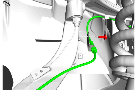
- Front Wheel Speed Sensor Bracket Bolt (1) » Remove
- Remove the front wheel speed sensor wiring harness bracket (2).
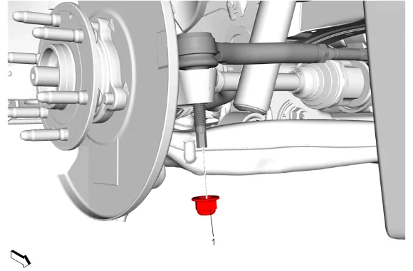
- Steering Linkage Outer Tie Rod Nut (1) » Remove
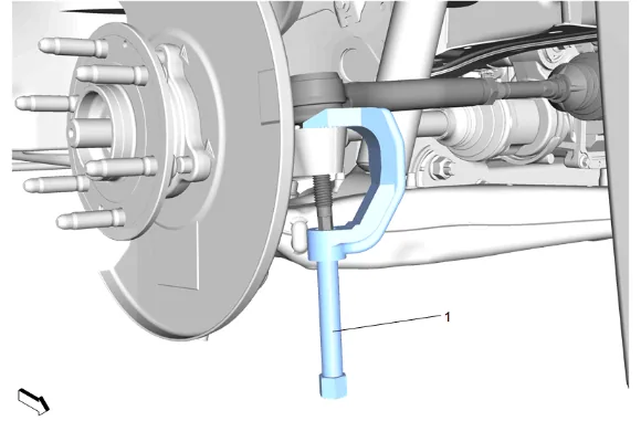
- Using CH-43631 Ball Joint Separator (1), remove the steering linkage outer tie rod from the steering knuckle.
- Support the lower control arm with a suitable jack stand.

- Front Stabilizer Shaft Link Nut (1) » Remove
- Front Stabilizer Shaft Link @ Lower Control Arm » Remove
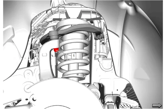
- Front Upper Control Arm Ball Stud Nut (1) » Loosen
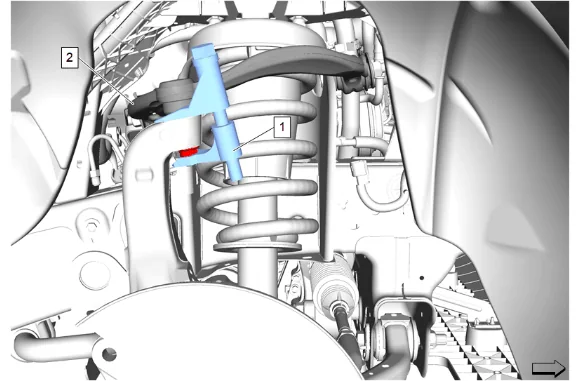
- Using the CH-42188-B Ball Joint Separator (1), separate the right front upper control arm (2) from the steering knuckle.
- Remove the CH-42188-B Ball Joint Separator (1) from the right front upper control arm (2) and the steering knuckle.
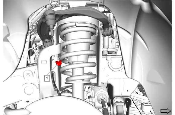
- Front Upper Control Arm Ball Stud Nut (1) » Remove
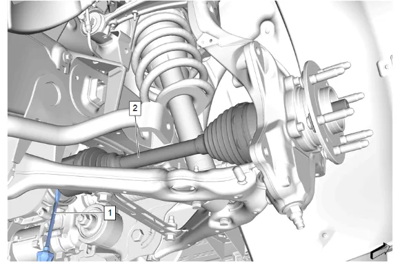
- Using a suitable flat bladed tool (1), release the front wheel drive half shaft (2) from the front differential carrier.
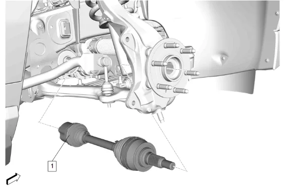
- Remove the front wheel drive half shaft (1) from the front axle.
- Remove the front wheel drive half shaft (1) from the wheel hub.
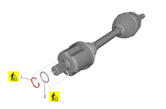
- Front Wheel Drive Shaft Retaining Ring (1) » Remove and DISCARD
- Front Wheel Drive Shaft Seal (2) » Remove and DISCARD
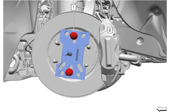
- Install the DT-45859 Axle Remover (2) to the front wheel hub and secure with 2 wheel nuts (1) hand tightened.
- Using the DT-45859 Axle Remover (2), release the front wheel drive half shaft from the front wheel hub.
- Remove the 2 wheel nuts (1) and the DT-45859 Axle Remover (2) from the front wheel hub.
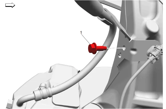
- Front Brake Hose Bracket Bolt (1) » Remove
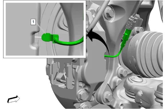
- { If equipped } Front Disc Brake Pad Wear Sensor (1) @ Front Brake Caliper » Remove
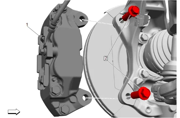
- Front Brake Caliper Bolt (2) » Remove [2x]
- Remove the brake caliper and support with heavy mechanics wire. (1)
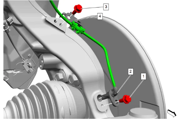
- Front Wheel Speed Sensor Bolt (1) » Remove
- Front Wheel Speed Sensor (2) » Remove
- Front Wheel Speed Sensor Bracket Bolt (3) » Remove
- Front Wheel Speed Sensor Bracket (4) » Remove
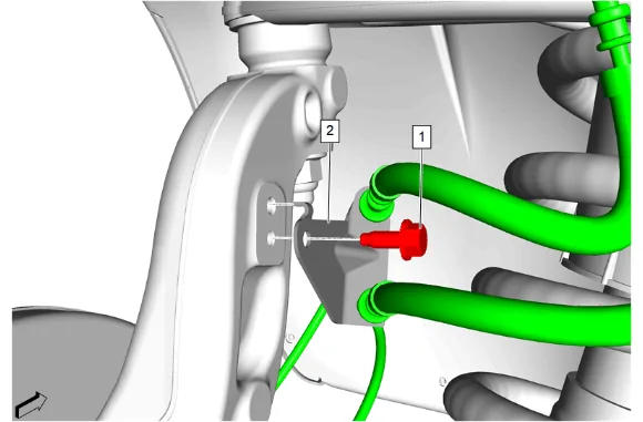
- Front Wheel Speed Sensor Bracket Bolt (1) » Remove
- Remove the front wheel speed sensor wiring harness bracket (2).
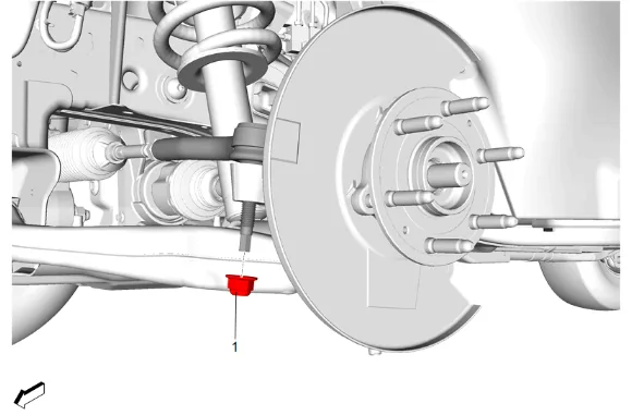
- Steering Linkage Outer Tie Rod Nut (1) » Remove
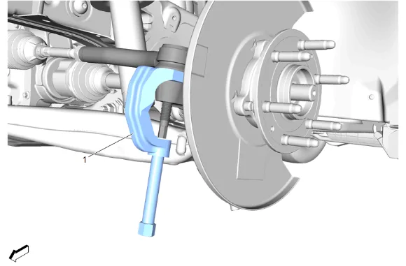
- Using CH-43631 Ball Joint Separator (1), remove the steering linkage outer tie rod from the steering knuckle.
- Support the lower control arm with a suitable jack stand.
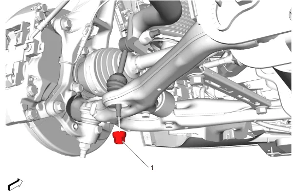
- Front Stabilizer Shaft Link Nut (1) » Remove
- Front Stabilizer Shaft Link @ Lower Control Arm » Remove
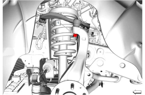
- Front Upper Control Arm Ball Stud Nut (1) » Loosen
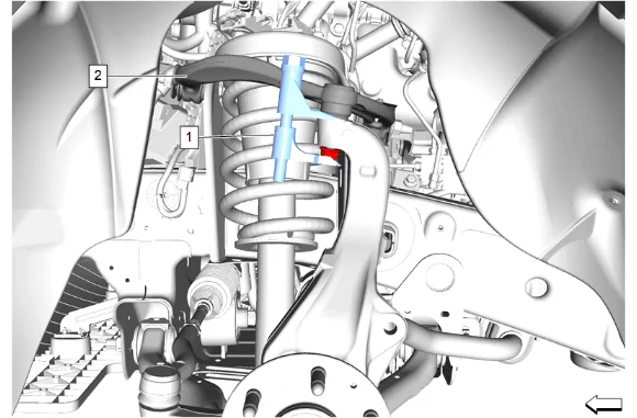
- Using the CH-42188-B Ball Joint Separator (1), separate the left front upper control arm (2) from the steering knuckle.
- Remove the CH-42188-B Ball Joint Separator (1) from the left front upper control arm (2) and the steering knuckle.
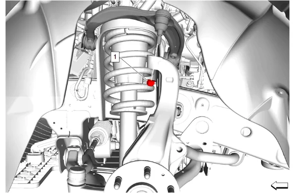
- Front Upper Control Arm Ball Stud Nut (1) » Remove
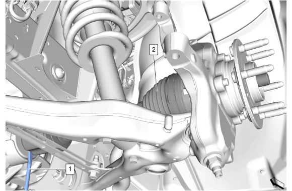
- Using a suitable flat bladed tool (1), release the front wheel drive half shaft (2) from the front differential carrier.
-
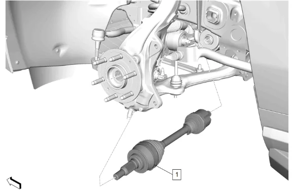
Remove the front wheel drive half shaft (1) from the front axle.
-
Remove the front wheel drive half shaft (1) from the wheel hub.
-
Front Wheel Drive Shaft Retaining Ring (1) » Remove and DISCARD
-
Front Wheel Drive Shaft Seal (2) » Remove and DISCARD
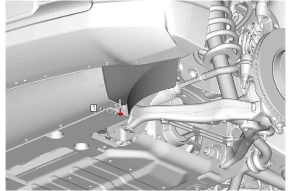
- { If equipped } Front Tire Front Air Deflector Bolt (1) » Remove
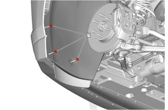
- Front Wheelhouse Liner Bolt (1) » Remove [3x]
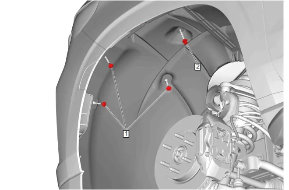
- Front Wheelhouse Liner Bolt (1) » Remove [3x]
- Front Wheelhouse Liner Retainer (2) » Remove
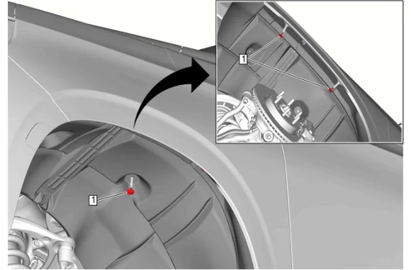
- Front Wheelhouse Liner Bolt (1) » Remove [3x]
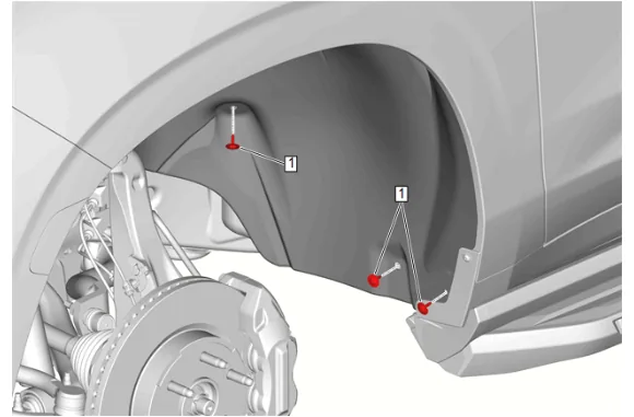
- Front Wheelhouse Liner Bolt (1) » Remove [3x]
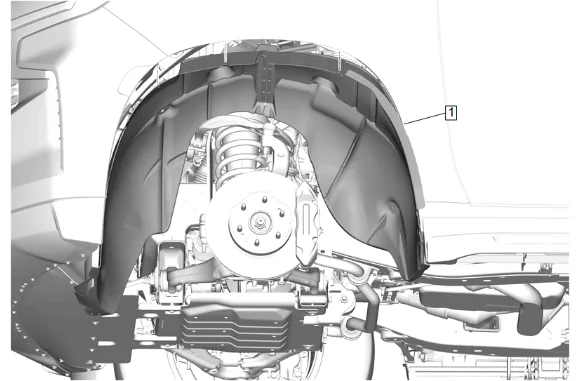
- Front Wheelhouse Liner (1) » Remove
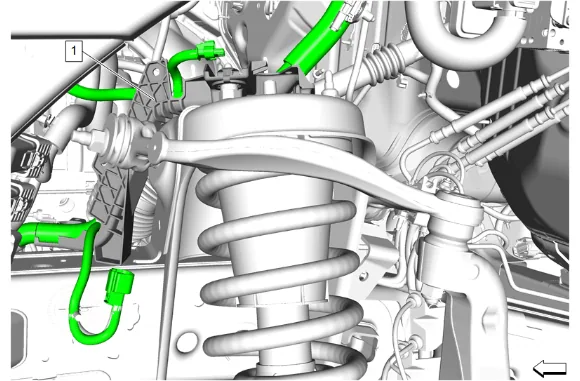
- Unclip and reposition the chassis wiring harness bracket (1) away from the frame shock tower.
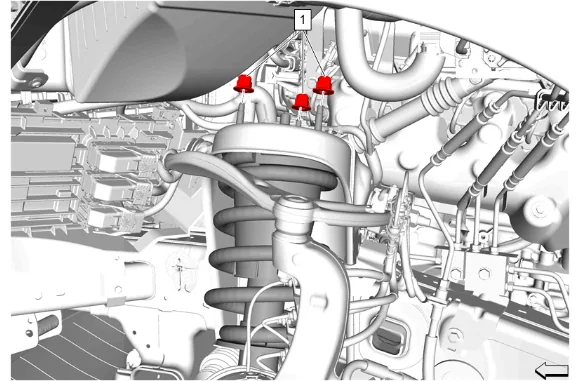
- Front Shock Absorber Nut (1) » Remove [3x]
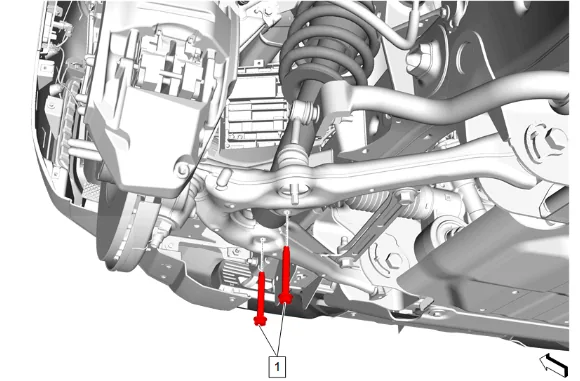
- Front Shock Absorber Bolt (1) » Remove [2x]
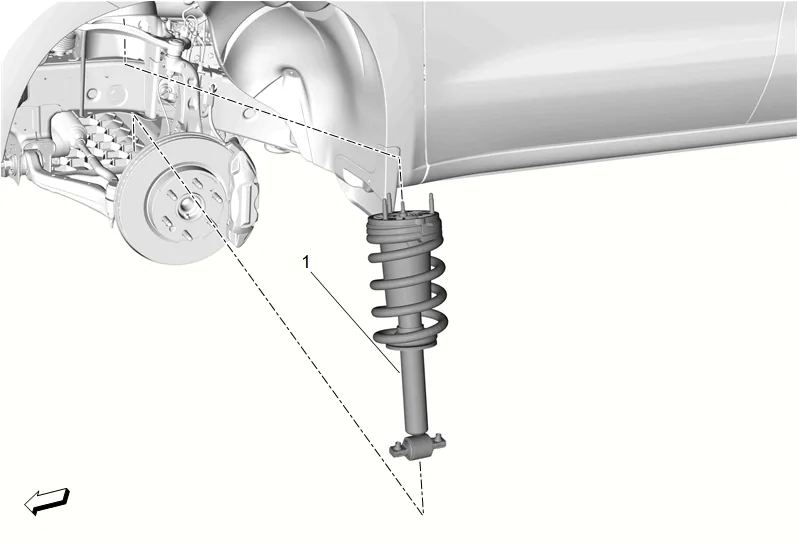
- {If Equipped} Disconnect the electrical connector at the shock absorber.
- Front Shock Absorber (1) » Remove
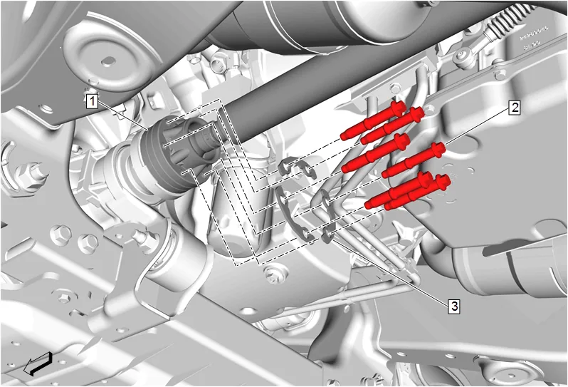
- Mark a reference point between the front axle propeller shaft (1) and the front differential drive pinion gear yoke.
- Front Axle Propeller Shaft Bolt (2) » Remove [6x]
- Front Axle Propeller Shaft Washer (3) » Remove [3x]
- Front Axle Propeller Shaft » Reposition away
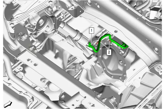
- Disconnect the front drive axle actuator electrical connector (1).
- Release the two harness retainers (2) and reposition harness.
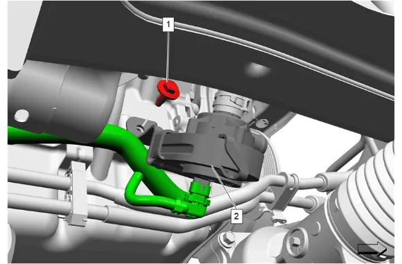
- { With L84, L87 } Electrical Connector @ Heater Coolant Pump (2) » Disconnect 80.1. Heater Water Auxiliary Pump Bolt (1) » Remove 80.2. Remove the heater coolant pump and heater water auxiliary pump bracket (2) as assembly and position aside.
- Support the front axle with a hydraulic jack.
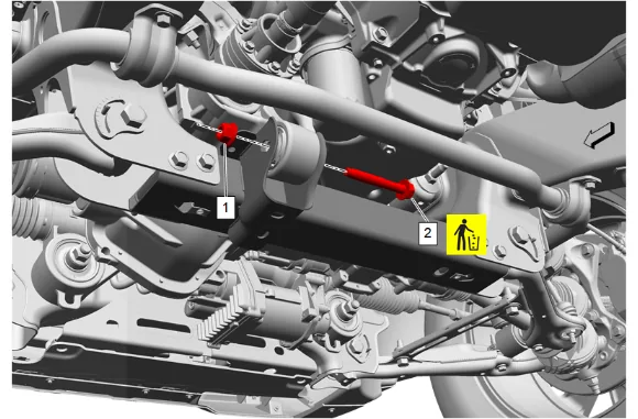
- Front Differential Carrier Nut (1) » Remove
- Front Differential Carrier Bolt (2) » Remove and DISCARD
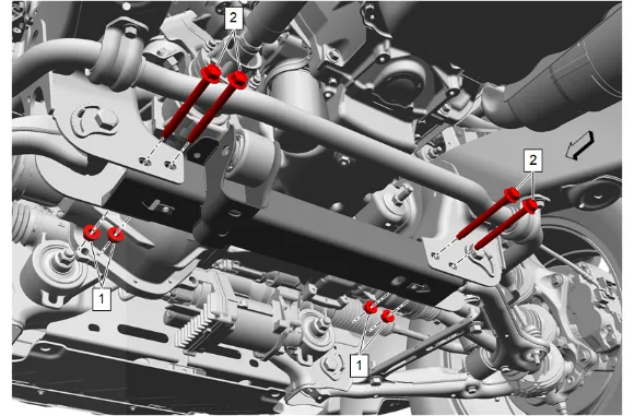
- Drivetrain and Front Suspension Frame Reinforcement Nut (1) » Remove [4x]
- Drivetrain and Front Suspension Frame Reinforcement Bolt (2) » Remove [4x]
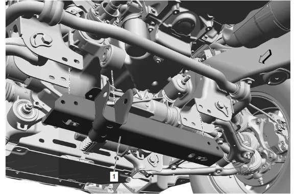
- Drivetrain and Front Suspension Frame Front Crossmember (1) » Remove
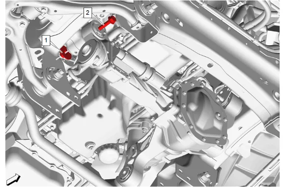
- Front Differential Carrier Bracket Nut (1) » Remove
- Front Differential Carrier Bolt (2) » Remove
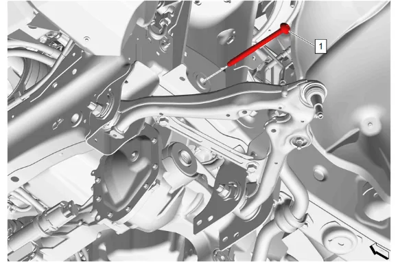
- Front Differential Carrier Bolt (1) » Remove
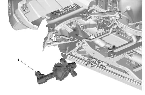
- Front Axle Vent Hose » Disconnect
- Front Axle (1) » Remove
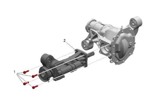
- Front Drive Axle Inner Shaft Housing Bolt (1) » Remove [4x]
- Front Drive Axle Inner Shaft Housing (2) » Remove
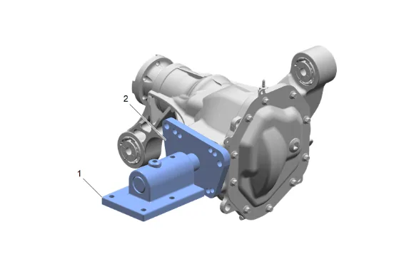
- Install the DT-52297 Front Axle Holding Fixture (2) to the front axle carrier using the front axle shaft tube mounting holes and attach to the DT-3289-20 Holding Fixture (1).
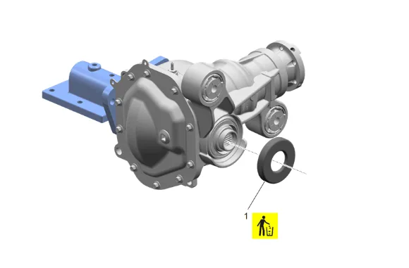
- Front Wheel Drive Shaft Slinger (1) » Remove and DISCARD
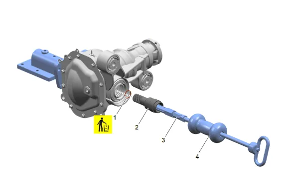
- Using EN-47966 Oil Control Valve Seal Remover (3) and GE-02619-A Slide Hammer w/Adapter (4), Remove the front wheel drive shaft (2).
- Front Drive Axle Inner Shaft Retaining Ring (1) » Remove and DISCARD
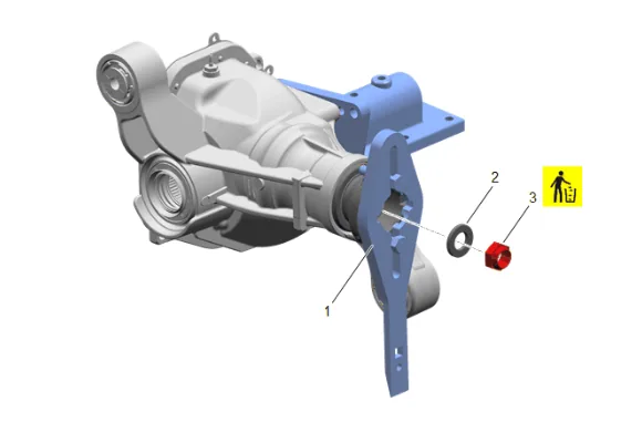
- Using DT-52506 Pinion Flange Holder and Remover (1) with the DT-08614-20 Flange Retaining Bolts, Remove and DISCARD the front differential drive pinion gear nut (3).
- Front Differential Drive Pinion Gear Washer (2) » Remove
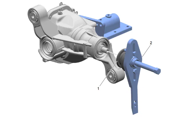
- Using DT-52506 Pinion Flange Holder and Remover (2) with the DT-08614-20 Flange Retaining Bolts, Remove the front differential drive pinion gear yoke (1).
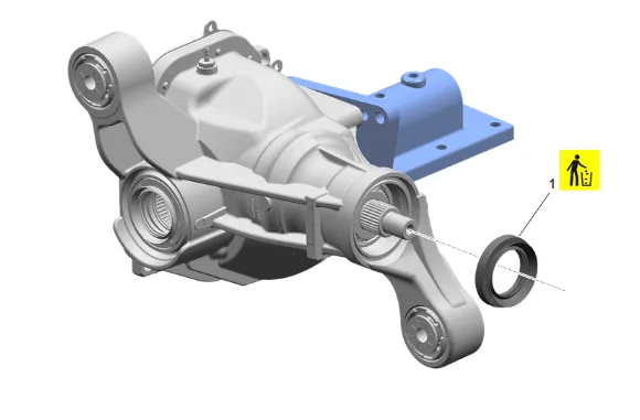
- Front Differential Drive Pinion Gear Seal (1) » Remove and DISCARD
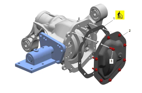
- Front Differential Carrier Cover Bolt (3) » Remove [10x]
- Front Differential Carrier Cover (2) » Remove
- Front Differential Carrier Cover Gasket (1) » Remove and DISCARD
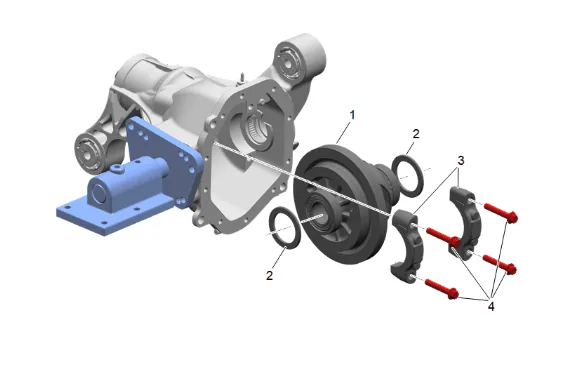
- Front Differential Bearing Cap Bolt (4) » Remove [4x]
- Front Axle Hub Cap (3) » Remove [2x]
- Front Differential Carrier Bearing Shim (2) » Remove [2x]
- Front Differential (1) » Remove
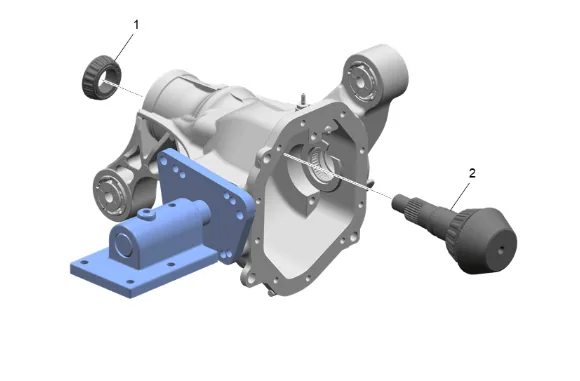
- Front Differential Drive Pinion Gear (2) » Remove
- Front Differential Drive Pinion Gear Bearing - Outer (1) » Remove
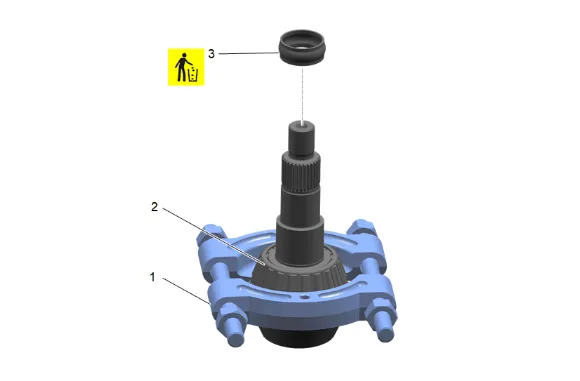
- Front Differential Drive Pinion Gear Bearing Spacer (3) » Remove and DISCARD
- Using DT-22912-B Bearing Remover (1) and shop press, Remove the differential drive pinion gear inner bearing (2).
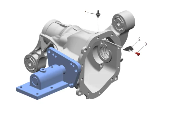
- Front Differential Carrier Vent Hose Connector (1) » Remove
- Front Differential Carrier Shield Bolt (3) » Remove
- Front Differential Drive Pinion Gear Lube Dam (2) » Remove
- Remove the DT-52297 Front Axle Holding Fixture. Installation Procedure
-
Install the DT-52297 Front Axle Holding Fixture (2) to the front axle carrier using the front axle shaft tube mounting holes and attach to the DT-3289-20 Holding Fixture (1).
-
Front Differential Drive Pinion Gear Lube Dam (2) » Install
- Front Differential Carrier Shield Bolt (3) » Install and tighten — Fastener Specifications
- Front Differential Carrier Vent Hose Connector (1) » Install and tighten — Fastener Specifications
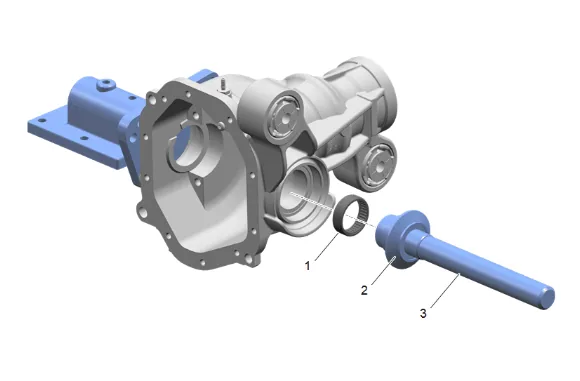
- Using DT-52555 Side Bearing Installer (2) and GE-8092 Driver Handle (3), Install front drive axle inner shaft bearing (1).
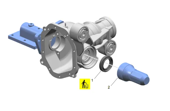
- Using DT-38869 Rear Extension Seal Installer (2), Install NEW front drive axle inner shaft seal (1).
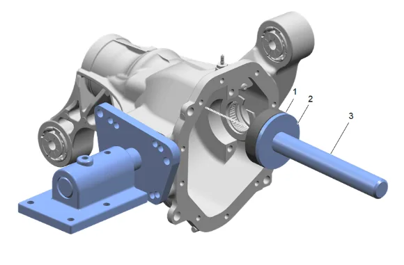
- Using DT-45704 Pinion Bearing Race Installer - Dana 248 (2) and GE-8092 Driver Handle (3), Install the differential drive pinion inner bearing cup (1).
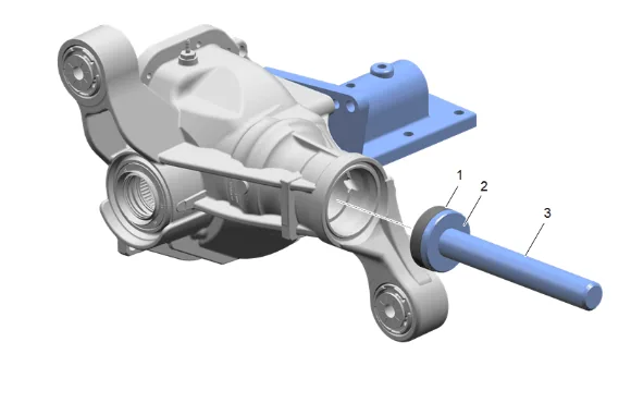
- Using DT-52556 Outer Pinion Bearing Cup Installer (2) and GE-8092 Driver Handle (3), Install the differential drive pinion outer bearing cup (1).
- Measure the pinion shim thickness needed, refer to Pinion Depth Adjustment.
- Install pinion shim onto pinion gear.
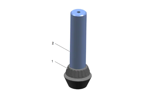
- Using DT-24433 Pinion Cone and Side Bearing Installer (2), Install the differential drive pinion gear inner bearing (1).
-
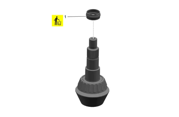
Front Differential Drive Pinion Gear Bearing Spacer (1) » Install NEW
-
Front Differential Drive Pinion Gear Bearing - Outer (1) » Install
-
Front Differential Drive Pinion Gear (2) » Install
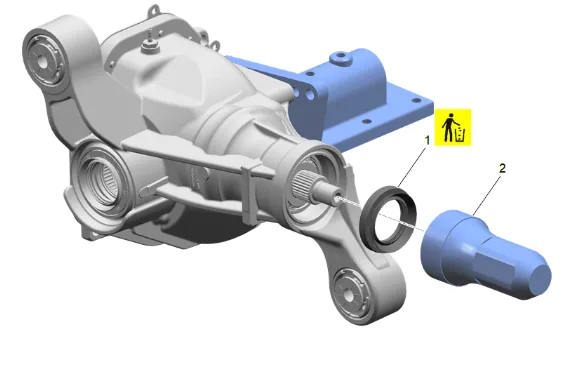
- Using DT-38869 Rear Extension Seal Installer (2), Install NEW the front differential drive pinion gear seal (1).
- Apply sealant to the pinion yoke splines. Adhesives, Fluids, Lubricants, and Sealers
- Apply grease to the pinion seal where it will contact the pinion gear yoke slinger. Adhesives, Fluids, Lubricants, and Sealers
-
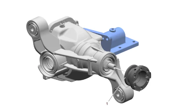
Front Differential Drive Pinion Gear Yoke (1) » Install
-
Front Differential Drive Pinion Gear Washer (2) » Install
-
Using DT-52506 Pinion Flange Holder and Remover (1) with the DT-08614-20 Flange Retaining Bolts, Install NEW front differential drive pinion gear nut (3) hand tight.
-
Tighten the front differential drive pinion gear nut (3) until there is no end play.
-
Measure the rotating torque of the pinion using an inch-pound torque wrench. Continue tightening the front differential drive pinion gear nut (3) until specified rotating torque is obtained, refer to Fastener Specifications.
-
Once the specified torque is obtained, rotate the pinion several times to ensure the bearings have seated. Recheck the rotating torque and adjust if necessary.
-
Measure the differential bearing shim thickness needed, refer to Differential Carrier Bearing Preload Adjustment.
-
Measure and adjust the backlash, refer to Backlash Inspection and Adjustment.
-
Front Differential (1) » Install
-
Front Differential Carrier Bearing Shim (2) » Install [2x]
-
Front Axle Hub Cap (3) » Install [2x]
-
Front Differential Bearing Cap Bolt (4) » Install and tighten [4x] — Fastener Specifications
-
If NEW threaded components are being installed, loosen the adhesive using a metal pick or similar tool before proceeding. If threaded components are reused, prepare the threaded components using the following steps: 30.1. Remove any loose cured adhesive from the external threads of the components using a lint free cloth. 30.2. Thread the cleaned components into the internal mating threads and remove to loosen trapped cured adhesive. 30.3. Apply thread locking adhesive to the external threads of the components. Adhesives, Fluids, Lubricants, and Sealers 30.4. Ensure there are no gaps in the thread locking adhesive once applied to the component.
-
Front Differential Carrier Cover Gasket (1) » Install NEW
-
Front Differential Carrier Cover (2) » Install
-
Front Differential Carrier Cover Bolt (3) » Install and tighten [10x] — Fastener Specifications
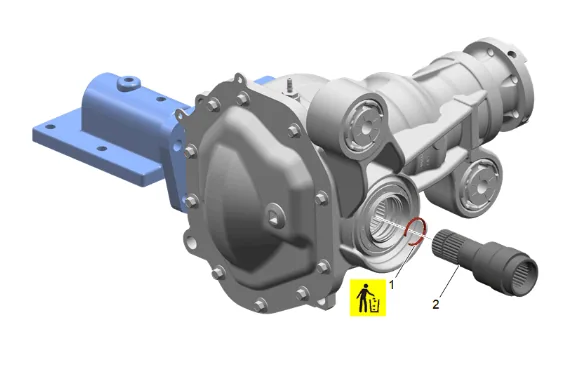
- Front Drive Axle Inner Shaft Retaining Ring (1) » Install NEW
- Front Wheel Drive Shaft (2) » Install
-
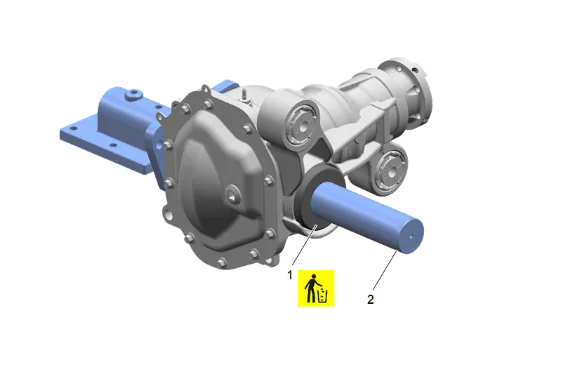
Using DT-35512 Inner Pinion Bearing Installer (2), Install NEW front wheel drive shaft slinger (1).
-
Remove the DT-52297 Front Axle Holding Fixture.
-
If NEW threaded components are being installed, loosen the adhesive using a metal pick or similar tool before proceeding. If threaded components are reused, prepare the threaded components using the following steps: 38.1. Remove any loose cured adhesive from the external threads of the components using a lint free cloth. 38.2. Thread the cleaned components into the internal mating threads and remove to loosen trapped cured adhesive. 38.3. Apply thread locking adhesive to the external threads of the components. Adhesives, Fluids, Lubricants, and Sealers 38.4. Ensure there are no gaps in the thread locking adhesive once applied to the component.
-
Front Drive Axle Inner Shaft Housing (2) » Install
-
Front Drive Axle Inner Shaft Housing Bolt (1) » Install and tighten [4x] — Fastener Specifications
- Front Axle (1) » Install
- Front Axle Vent Hose » Connect
-
Front Differential Carrier Bolt (1) » Install and tighten — Fastener Specifications
-
Front Differential Carrier Bolt (2) » Install
-
Front Differential Carrier Bracket Nut (1) » Install and tighten — Fastener Specifications
-
Drivetrain and Front Suspension Frame Front Crossmember (1) » Install
-
Drivetrain and Front Suspension Frame Reinforcement Bolt (2) » Install [4x]
-
Using the EN-45059-A Angle Meter, Install and tighten the 4 drivetrain and front suspension frame reinforcement nuts (1). Fastener Specifications
- Front Differential Carrier Bolt (2) » Install NEW
- Front Differential Carrier Nut (1) » Install
- Using the EN-45059-A Angle Meter, Tighten the front differential carrier nut (1). Fastener Specifications
-
{ With L84, L87 } Install the heater coolant pump and heater water auxiliary pump bracket (2) as assembly. 52.1. Heater Water Auxiliary Pump Bolt (1) » Install and tighten — Fastener Specifications 52.2. Electrical Connector @ Heater Coolant Pump (2) » Connect
-
Connect the front drive axle actuator electrical connector (1).
-
Reposition the harness and secure the two harness retainers (2).
-
Clean the residue from the threaded holes of the front differential drive pinion gear yoke with denatured alcohol and allow to dry.
-
If NEW threaded components are being installed, loosen the adhesive using a metal pick or similar tool before proceeding. If threaded components are reused, prepare the threaded components using the following steps: 56.1. Remove any loose cured adhesive from the external threads of the components using a lint free cloth. 56.2. Thread the cleaned components into the internal mating threads and remove to loosen trapped cured adhesive. 56.3. Apply thread locking adhesive to the external threads of the components. Adhesives, Fluids, Lubricants, and Sealers 56.4. Ensure there are no gaps in the thread locking adhesive once applied to the component.
-
Front Axle Propeller Shaft (1) » Reposition
-
Align the reference marks made between the front axle propeller shaft (1) and the front differential drive pinion gear yoke.
-
Front Axle Propeller Shaft Washer (3) » Install [3x]
-
Install the 6 front axle propeller shaft bolts (2) and tighten in a crisscross pattern. Fastener Specifications
- Apply anti-corrosion wax to the frame shock tower. Anti-Corrosion Treatment and Repair
- Front Shock Absorber (1) » Install
- {If Equipped} Connect the electrical connector at the shock absorber.
-
Front Shock Absorber Bolt (1) » Install and tighten [2x] — Fastener Specifications
-
Front Shock Absorber Nut (1) » Install and tighten [3x] — Fastener Specifications
-
Front Wheelhouse Liner (1) » Install
- Front Wheelhouse Liner Bolt (1) » Install and tighten [3x] — Fastener Specifications
- Front Wheelhouse Liner Bolt (1) » Install and tighten [3x] — Fastener Specifications
- Front Wheelhouse Liner Retainer (2) » Install
- Front Wheelhouse Liner Bolt (1) » Install and tighten [3x] — Fastener Specifications
-
Front Wheelhouse Liner Bolt (1) » Install and tighten [3x] — Fastener Specifications
-
{ If equipped } Front Tire Front Air Deflector Bolt (1) » Install and tighten — Fastener Specifications
-
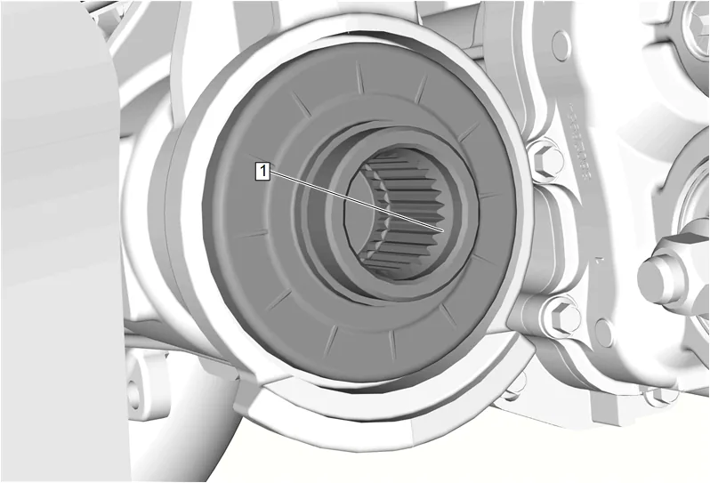
Remove any buildup from the front differential carrier output shaft lead in chamfer (1) using an abrasive pad and wipe clean with a shop cloth.
-
Front Wheel Drive Shaft Seal (2) » Install NEW
-
Front Wheel Drive Shaft Retaining Ring (1) » Install NEW
-
Apply a thin coating of grease to the splines of the front wheel drive half shaft and front differential carrier output shaft. Adhesives, Fluids, Lubricants, and Sealers
-
Install the front wheel drive half shaft (1) into the wheel hub.
-
Install the front wheel drive half shaft (1) into the front axle.
-
Ensure that the left front wheel drive half shaft (1) is fully seated in front differential carrier by pulling on the inner joint.
-
Support the steering knuckle with a suitable jack stand.
-
Front Upper Control Arm Ball Stud Nut (1) » Install and tighten — Fastener Specifications
-
Front Stabilizer Shaft Link @ Front Lower Control Arm » Install
-
Front Stabilizer Shaft Link Nut (1) » Install and tighten — Fastener Specifications
-
Steering Linkage Outer Tie Rod Nut (1) » Install and tighten — Fastener Specifications
-
Install the front wheel speed sensor wiring harness bracket (2).
-
Front Wheel Speed Sensor Bracket Bolt (1) » Install and tighten — Fastener Specifications
-
Front Wheel Speed Sensor (2) » Install
-
Front Wheel Speed Sensor Bolt (1) » Install and tighten — Fastener Specifications
-
Front Wheel Speed Sensor Bracket (4) » Install
-
Front Wheel Speed Sensor Bracket Bolt (3) » Install and tighten — Fastener Specifications
-
If NEW threaded components are being installed, loosen the adhesive using a metal pick or similar tool before proceeding. If threaded components are reused, prepare the threaded components using the following steps: 91.1. Remove any loose cured adhesive from the external threads of the components using a lint free cloth. 91.2. Thread the cleaned components into the internal mating threads and remove to loosen trapped cured adhesive. 91.3. Apply thread locking adhesive to the external threads of the components. Adhesives, Fluids, Lubricants, and Sealers 91.4. Ensure there are no gaps in the thread locking adhesive once applied to the component.
-
Front Brake Caliper (1) » Install
-
Front Brake Caliper Bolt (2) » Install and tighten [2x] — Fastener Specifications
-
Front Brake Hose Bracket Bolt (1) » Install and tighten — Fastener Specifications
-
{ If equipped } Front Disc Brake Pad Wear Sensor (1) @ Front Brake Caliper » Install
-
Remove any buildup from the front differential carrier output shaft lead in chamfer (1) using an abrasive pad and wipe clean with a shop cloth.
-
Front Wheel Drive Shaft Seal (2) » Install NEW
-
Front Wheel Drive Shaft Retaining Ring (1) » Install NEW
-
Apply a thin coating of grease to the splines of the front wheel drive half shaft and front differential carrier output shaft. Adhesives, Fluids, Lubricants, and Sealers
-
Install the front wheel drive half shaft (1) into the wheel hub.
-
Install the front wheel drive half shaft (1) into the front axle.
-
Ensure that the right front wheel drive half shaft (1) is fully seated in front differential carrier by pulling on the inner joint.
-
Support the steering knuckle with a suitable jack stand.
-
Front Upper Control Arm Ball Stud Nut (1) » Install and tighten — Fastener Specifications
-
Front Stabilizer Shaft Link @ Lower Control Arm » Install
-
Front Stabilizer Shaft Link Nut (1) » Install and tighten — Fastener Specifications
-
Steering Linkage Outer Tie Rod Nut (1) » Install and tighten — Fastener Specifications
-
Install the front wheel speed sensor wiring harness bracket (2).
-
Front Wheel Speed Sensor Bracket Bolt (1) » Install and tighten — Fastener Specifications
-
Front Wheel Speed Sensor (2) » Install
-
Front Wheel Speed Sensor Bolt (1) » Install and tighten — Fastener Specifications
-
Front Wheel Speed Sensor Bracket (4) » Install
-
Front Wheel Speed Sensor Bracket Bolt (3) » Install and tighten — Fastener Specifications
-
If NEW threaded components are being installed, loosen the adhesive using a metal pick or similar tool before proceeding. If threaded components are reused, prepare the threaded components using the following steps: 114.1. Remove any loose cured adhesive from the external threads of the components using a lint free cloth. 114.2. Thread the cleaned components into the internal mating threads and remove to loosen trapped cured adhesive. 114.3. Apply thread locking adhesive to the external threads of the components. Adhesives, Fluids, Lubricants, and Sealers 114.4. Ensure there are no gaps in the thread locking adhesive once applied to the component.
-
Front Brake Caliper (1) » Install
-
Front Brake Caliper Bolt (2) » Install and tighten [2x] — Fastener Specifications
-
Front Brake Hose Bracket Bolt (1) » Install and tighten — Fastener Specifications
-
Have an assistant apply the brakes.
- Front Wheel Drive Shaft Nut (1) » Install NEW and tighten — Fastener Specifications
- Front Wheel Drive Shaft Nut (1) » Install NEW and tighten — Fastener Specifications
- Install the front tire and wheel assemblies. Tire and Wheel Removal and Installation
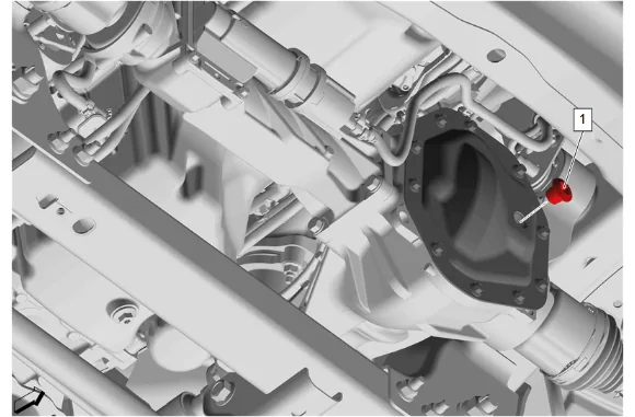
- Front Differential Carrier Oil Filler Plug (1) » Remove
- Inspect the gear lubricant level, it should be 16–22 mm (0.6-0.9 in) below the plug opening.
- If the level is low, add gear lubricant until the level is 16–22 mm (0.6-0.9 in) below the plug opening. Use the appropriate axle lubricant: Adhesives, Fluids, Lubricants, and Sealers
-
Front Differential Carrier Oil Filler Plug (1) » Install and tighten — Fastener Specifications
-
{with RC1} Install the underbody skid shield: 126.1. Underbody Skid Shield (3) » Install 126.2. Underbody Splash Shield Bolt (2) » Install and tighten [2x] — Fastener Specifications 126.3. Underbody Skid Shield Bolt (1) » Install and tighten [2x] — Fastener Specifications
-
{Without RC1} Install the underbody skid shield: 127.1. Underbody Skid Shield (2) » Install 127.2. Underbody Skid Shield Bolt (1) » Install and tighten [4x] — Fastener Specifications
-
Remove the support and lower the vehicle.
-
Connect the battery negative cable.