Table 1:
DuraSeal Splice Sleeve Reference
Table 2:
Ground Ring Terminal Terminated Lead Kit Reference
Special Tools
J-38125-8 GMNA Splice Sleeve Crimping Tool
EL-38125-10 Except GMNA Splice Sleeve Crimping Tool
EL-38125-5A Ultra Torch Special Tool
DuraSeal splice sleeves
For equivalent regional tools, refer to Special Tools.
Danger: In order to reduce the risk of personal injury, loss of high voltage isolation to ground and
higher system impedance, do not attempt to repair any HV wiring, connector, or terminal that
is damaged. High voltage coaxial type cables are not repairable. Never attempt to repair a
coaxial type cable. The entire cable/harness or component must be replaced. In order to
maintain system integrity and personal safety, never attempt to repair any high voltage wiring,
cables, or terminals. Performing this procedure on high voltage circuits may result in serious
injury or death.
Refer to: Folded-Over Wire Repair when splicing 2 different size wires.
Ground Ring Terminal Terminated Lead Kit Reference
Splice Sleeve Color
GM PN Single Ground Ring Terminated Lead Kit
GM PN Double Ground Ring Terminated Lead Kit
Wire Gauge mm² / (AWG)
Salmon (Yellow-Pink) 19300089
84976194
84976197
0.5 – 0.8/(18-26)
Blue 19300090
84976195
84976198
1.0 – 2.6(14-16)
Yellow 19300091
84976196
84976199
3.0 – 5.0(10-12)
Note: Refer to: Folded-Over Wire Repair when splicing 2 different size wires. Refer to the Table above for Proper tool usage information. This repair is only intended for the M6 Ground Stud. The Information in Table Below is for M6 Ground Ring Terminal Terminated lead Splicing. The kit includes the Splice Sleeves. If the Ground Stud and nut require repair Refer to: Ground Repair.
Open the harness by removing any tape:
Use a sewing seam ripper, available from sewing supply stores, in order to cut open the
harness in order to avoid wire insulation damage.
Use the DuraSeal splice sleeves on all types of insulation except Tefzel and coaxial.
Do not use the crimp and DuraSeal splice sleeve to form a splice with more than 2 wires
coming together.
Cut as little wire off the harness as possible. You may need the extra length of wire in order to
change the location of a splice.
Adjust splice locations so that each splice is at least 40 mm (1.5 in) away from the other splices,
harness branches, or connectors.
Strip the insulation:
When adding a length of wire to the existing harness, use the same size wire as the original
wire.
Perform one of the following items in order to find the correct wire size:
– Find the wire on the schematic and convert to regional wiring gauge size.
– If you are unsure of the wire size, begin with the largest opening in the wire stripper and
work down until achieving a clean strip of the insulation.
Strip approximately 5.0 mm (0.20 in) of insulation from each wire to be spliced.
Do not nick or cut any of the strands. Inspect the stripped wire for nicks or cut strands.
If the wire is damaged, repeat this procedure after removing the damaged section.
For high temperature wiring 150°C (302°F) continuous or 175°C (347°F) excursion, use high
temperature heat shrink tube (Raychem SCT1) over the DuraSeal splice area. Refer to High
Temperature Wiring Repairs below.
Select the proper DuraSeal splice sleeve according to the wire size. Refer to the table above, at the
beginning of the repair procedure for the color coding of the DuraSeal splice sleeves and the crimp
tool nests.
Wire to Wire Repair - Headliner — figure 1
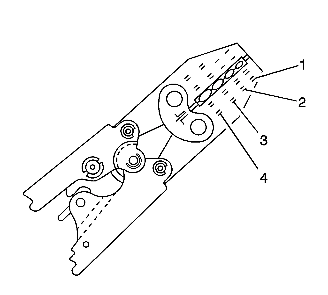
Non GMNA Crimping Tool EL-38125-10 Splice Sleeve Crimping Tool has four crimp nests. The largest
crimp nest (4) is used for crimping 5.0 and 3.0 mm² (10 and 12 gauge) wires. The second largest
crimp nest (3) is used for crimping 2.0 and 1.0 mm² (14 and 16 gauge) wires. The third largest
crimp nest (2) is used for crimping 0.75 and 0.50 mm² (18 and 20 gauge) wires. The smallest crimp
nest (1) is used for crimping 0.35 and 0.13 mm² (22 to 26 gauge) wires. The crimp nests are
referenced in the table (farther above) under the crimp tool nest color.
Wire to Wire Repair - Headliner — figure 2
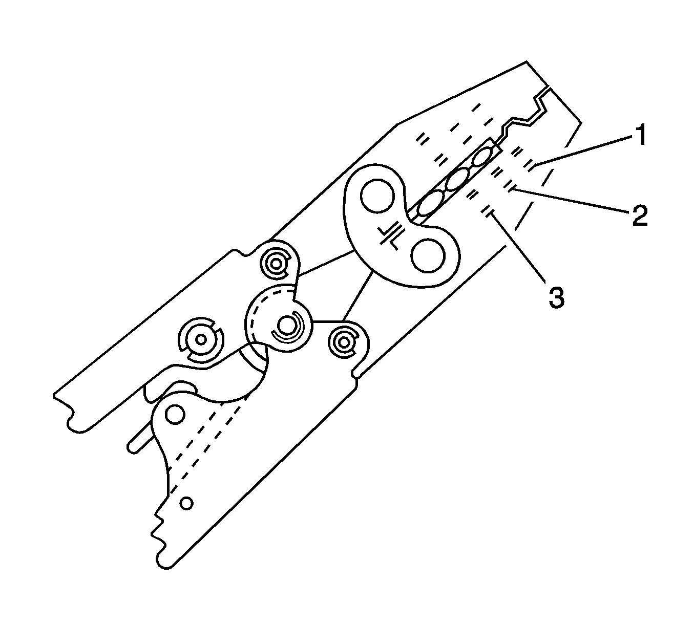
GMNA crimping tool J-38125-8 splice sleeve crimping tool has three crimp nests. The largest crimp
nest (3) is used for crimping 5.0 and 3.0 mm² (10 and 12 gauge). The second largest crimp nest (2)
is used for crimping 2.0 and 1.0 mm² (14 and 16 gauge) wires. The smallest crimp nest (1) is used
for crimping 0.75 and 0.50 mm² (18 and 20 gauge) wires. The crimp nests are referenced in the
table (farther above) under the crimp tool nest color.
Use the splice sleeve crimp tool in order to position the DuraSeal splice sleeve in the proper color
nest of the splice sleeve crimp tool. For the four crimp nest tool, use the three largest crimp nests to
crimp the splice sleeves. For the three crimp nest tool, use all three crimp nests to crimp the splice
sleeves. Use the four and three crimp tool diagrams (above) and the table (farther above) to match
the splice sleeve with the correct crimp nest. The crimp tool diagram call out numbers match the
numbers in the table (under crimp tool nest color).
Wire to Wire Repair - Headliner — figure 3
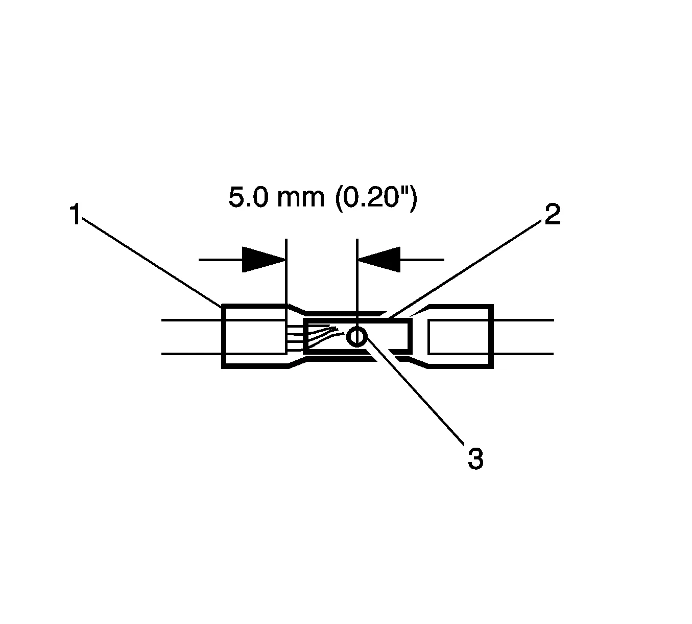
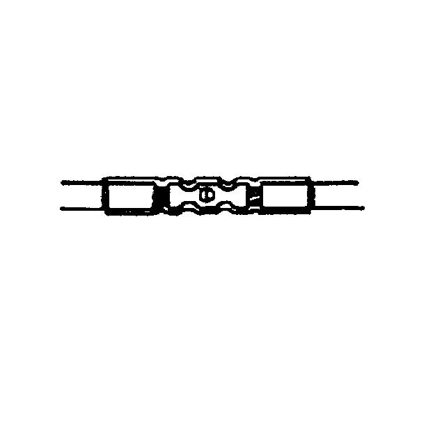
Place the DuraSeal splice sleeve in the nest. Ensure that the crimp falls midway between the end of
the barrel and the stop. The sleeve has a stop (3) in the middle of the barrel (2) in order to prevent
the wire (1) from going further. Close the hand crimper handles slightly in order to firmly hold the
DuraSeal splice sleeve in the proper nest.
Wire to Wire Repair - Headliner — figure 4
Insert the wire into the splice sleeve barrel until the wire hits the barrel stop. Refer to Folded-Over
Wire Repair for splicing wires 0.35 and 0.13 mm² (22 to 26 gauge) wires and for splicing wires of
different gauges.
Tightly close the handles of the crimp tool until the crimper handles open when released.
The crimper handles will not open until you apply the proper amount of pressure to the DuraSeal
splice sleeve. Repeat steps 4 and 6 for the opposite end of the splice.
Wire to Wire Repair - Headliner — figure 5
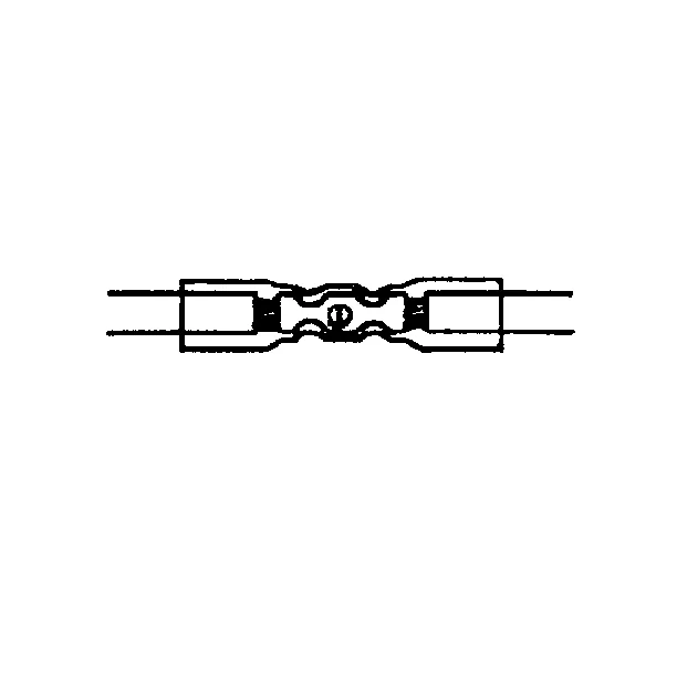
Using the EL-38125-5A Ultra Torch Special Tool, apply heat to the crimped area of the barrel.
Start in the middle and gradually move the heat barrel to the open ends of the tubing:
The tubing will shrink completely as the heat is moved along the insulation.
A small amount of sealant will come out of the end of the tubing when sufficient shrinkage is
achieved.
Weatherpack™ Wiring Repair
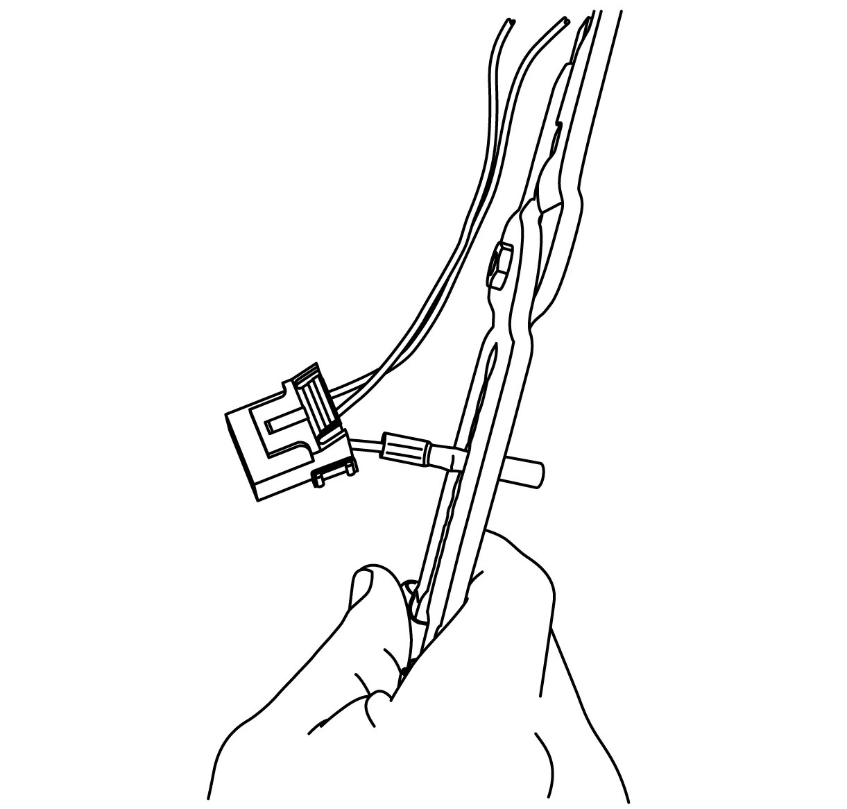
Insert the wire into the splice sleeve barrel until the wire hits the barrel stop. Refer to Folded-
Over Wire Repair for splicing wires 0.35 and 0.13 mm² (22 to 26 gauge) wires and for splicing
wires of different gauges.
Wire to Wire Repair - Headliner — figure 6
Tightly close the handles of the crimp tool until the crimper handles open when released.
The crimper handles will not open until you apply the proper amount of pressure to the
DuraSeal splice sleeve. Holding the DuraSEAL with one hand gently tug on the wire to ensure
it is crimped in the DuraSeal.
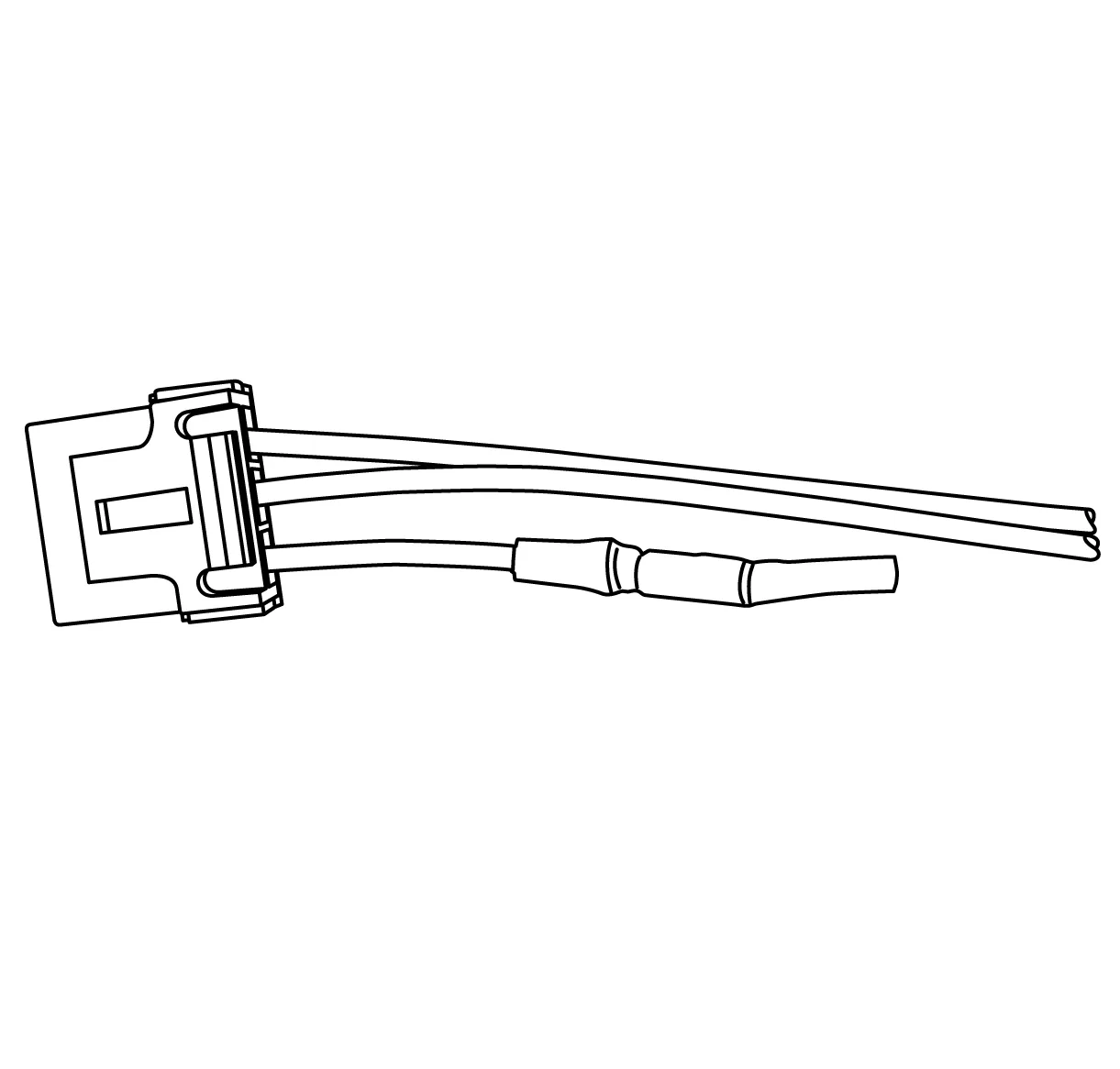
Using the EL-38125-5A Ultra Torch Special Tool, apply heat to the crimped area of the barrel.
Wire to Wire Repair - Headliner — figure 7
Start in the middle and gradually move the heat barrel to the open ends of the tubing:
The tubing will shrink completely as the heat is moved along the insulation.
A small amount of sealant will come out of the end of the tubing when sufficient
shrinkage is achieved.
Wire to Wire Repair - Headliner — figure 8
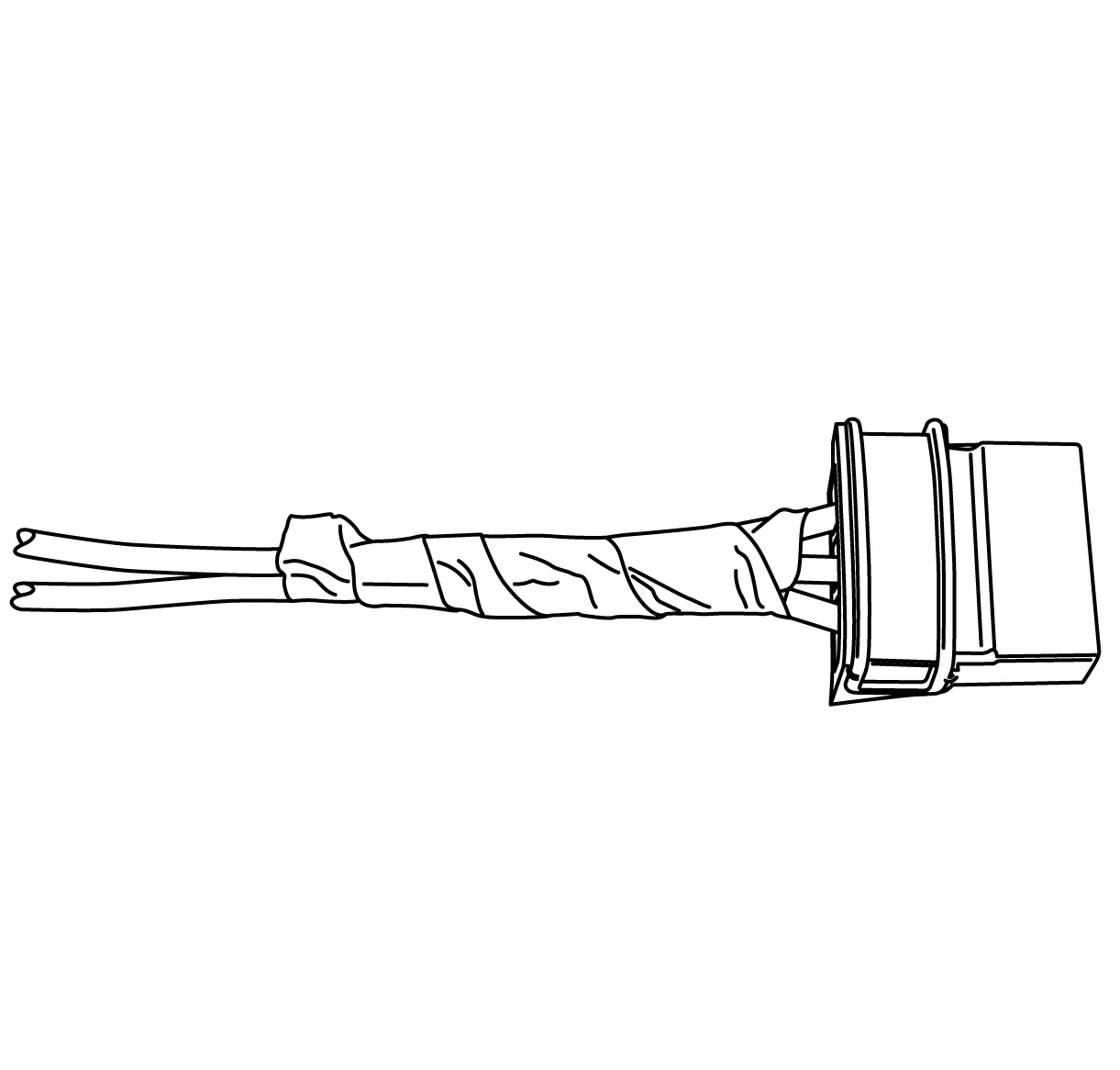
Tape the excess terminated lead(s) back into the harness. The tape should cover the harness
by 25 mm (1 Inch). Use care to make sure the taping does not cause strain on the wiring and
terminals, Improper taping can cause wire and terminal fretting.
High Temperature Wiring Repairs
Use the following procedures to perform high temperature wiring repairs: