Brake Pedal Assembly Replacement
Removal Procedure
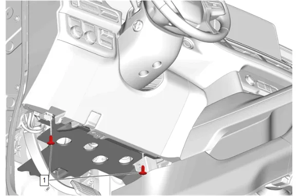
- Instrument Panel Lower Insulator Retainer (1) » Remove [2x]
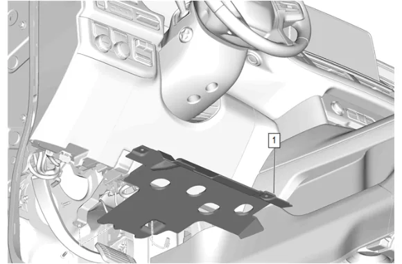
- Instrument Panel Lower Trim Panel Insulator (1) » Remove
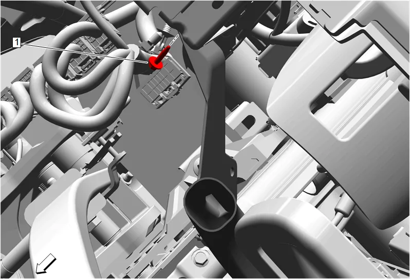
- Floor Front Air Outlet Duct Bolt (1) » Remove
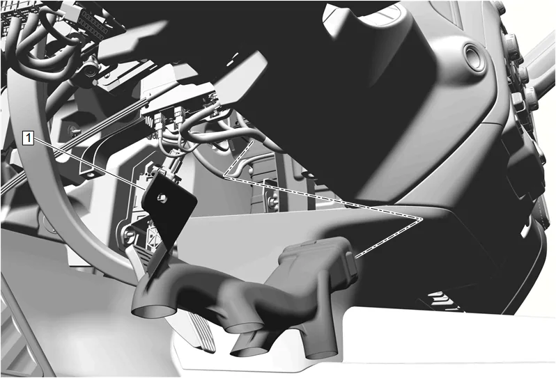
- Floor Front Air Outlet Duct - Left Side (1) » Remove
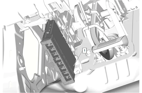
- Disconnect the electrical connectors.
- Release the retaining tabs.
- Body Control Module (1) » Remove
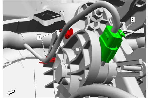
- Wiring Harness Retainer (1) @ Brake Pedal » Remove [2x]
- Brake Pedal Position Sensor Electrical Connector (2) » Disconnect
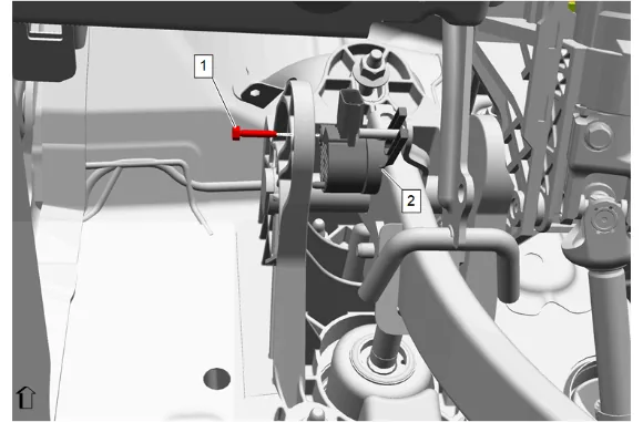
- Brake Pedal Position Sensor Bolt (1) » Remove
- Brake Pedal Position Sensor (2) » Remove
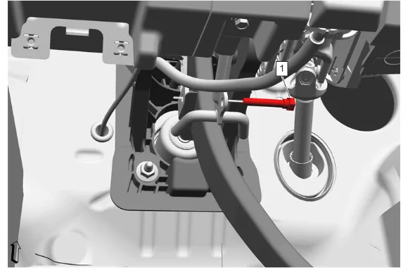
- Brake Pedal Push Rod Bolt (1) » Remove
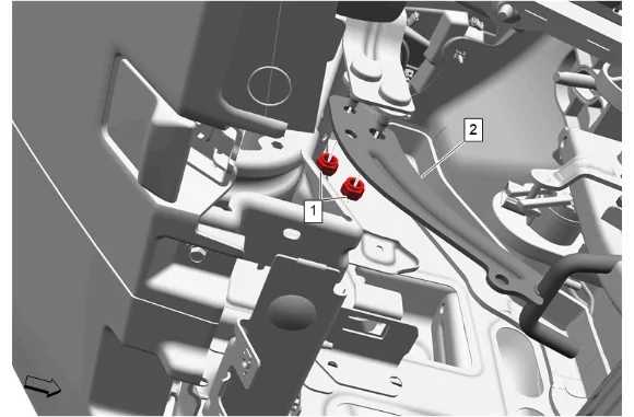
- Instrument Panel Tie Bar Bracket Nut (1) » Remove [2x]
- Instrument Panel Tie Bar Bracket (2) » Remove
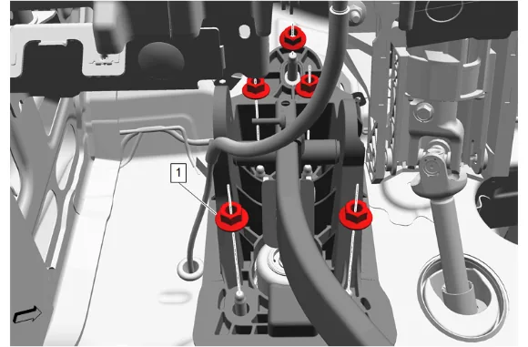
- Brake Pedal Nut (1) » Remove [5x]
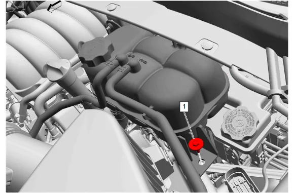
- Radiator Surge Tank Bolt (1) » Remove
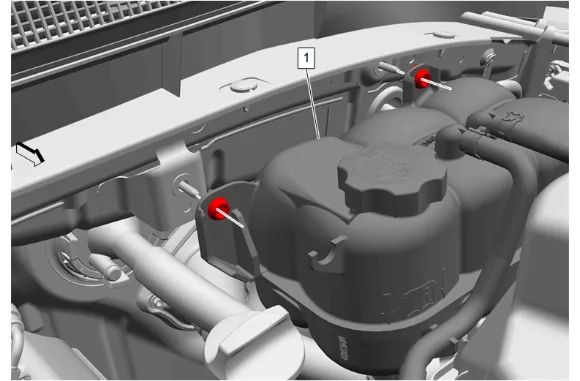
- Without disconnecting the hoses, remove the radiator surge tank and position aside. (1)
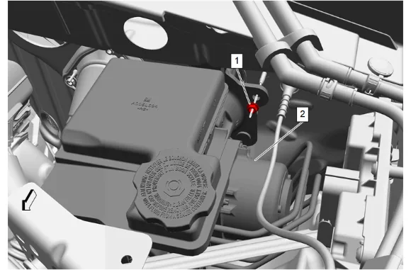
- Remove the brake master cylinder adapter nut (1) and pull the brake master cylinder (2) away from the fire wall to gain clearance for the removal of the brake pedal.
-
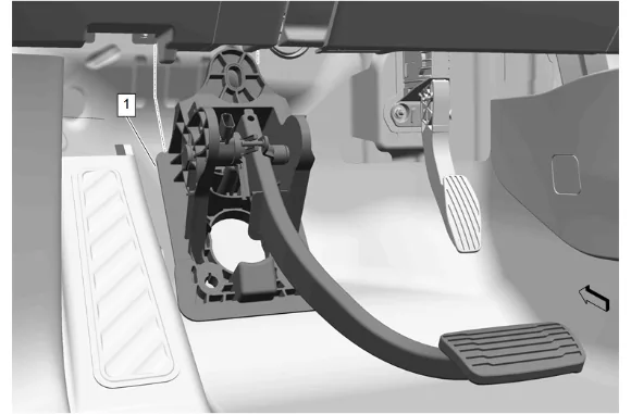
Brake Pedal (1) » Remove Installation Procedure
-
Brake Pedal (1) » Install
-
Brake Pedal Nut (1) » Install and tighten [5x] — Fastener Specifications
-
Instrument Panel Tie Bar Bracket (2) » Install
-
Instrument Panel Tie Bar Bracket Nut (1) » Install and tighten [2x] — Fastener Specifications
-
Brake Master Cylinder (2) » Install
-
Brake Master Cylinder Adapter Nut (2) » Install and tighten — Fastener Specifications
-
Radiator Surge Tank (1) » Install
-
Radiator Surge Tank Bolt (1) » Install and tighten — Fastener Specifications
-
If a NEW threaded component is being installed, loosen the adhesive using a metal pick or similar tool before proceeding. If threaded component is reused, prepare the threaded component using the following steps: 9.1. Remove any loose cured adhesive from the external threads of the component using a lint free cloth. 9.2. Thread the cleaned component into the internal mating threads and remove to loosen trapped cured adhesive. 9.3. Apply thread locking adhesive to the external threads of the component. Adhesives, Fluids, Lubricants, and Sealers 9.4. Ensure there are no gaps in the thread locking adhesive once applied to the component.
-
Brake Pedal Push Rod Bolt (1) » Install and tighten — Fastener Specifications
-
Brake Pedal Position Sensor (2) » Install
-
Brake Pedal Position Sensor Bolt (1) » Install and tighten — Fastener Specifications
-
Wiring Harness Retainer (1) @ Brake Pedal » Install [2x]
-
Brake Pedal Position Sensor Electrical Connector (2) » Connect
-
Body Control Module (1) » Install
-
Secure the retaining tabs.
-
Connect the electrical connectors.
-
Floor Front Air Outlet Duct - Left Side (1) » Install
-
Floor Front Air Outlet Duct Bolt (1) » Install and tighten — Fastener Specifications
-
Instrument Panel Lower Trim Panel Insulator (1) » Install
-
Instrument Panel Lower Insulator Retainer (1) » Install [2x]
-
Calibrate the brake pedal position sensor. Brake Pedal Position Sensor Calibration