Ball Joint Inspection
Special Tools GE-8001 Dial Indicator Set Equivalent regional tools: Special Tools
- Raise and support the vehicle. Lifting and Jacking the Vehicle
- Clean and inspect the ball joint seal for cuts or tears. If the ball joint seal is damaged, replace the applicable front upper control arm. Front Upper Control Arm Replacement - Left Side or Front Upper Control Arm Replacement - Right Side
- Support the front lower control arm with a floor stand as far outboard as possible and raise the suspension until the lower control arm moves 25 mm (0.98 in).
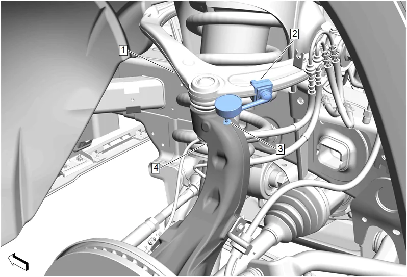
- Install the base (2) of the GE-8001 Dial Indicator Set, or suitable dial indicator to the front upper control arm (1) as shown.
- Install the dial indicator of the GE-8001 Dial Indicator Set with the contact point (3) positioned at the steering knuckle (4) as shown.
- Apply downward force to the front upper control arm (1) and zero the indicator.
- Apply upward force to the front upper control arm (1) and check the dial indicator. Record the measurement
- If the recorded dial indicator reading is more than 0.50 mm (0.020 in), replace the applicable front upper control arm. Front Upper Control Arm Replacement - Left Side or Front Upper Control Arm Replacement - Right Side
- Remove the support and lower the vehicle.