Rear Programmable Mode Valve Actuator Replacement (with C69, without 9C1)
Rear Programmable Mode Valve Actuator Replacement (with C69, without 9C1) Removal Procedure
- Disable the SIR system. SIR Disabling and Enabling
- Remove the 3rd row seat. 3rd Row Seat Removal and Installation
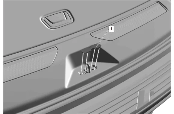
- Using the appropriate tool release the detents to remove the liftgate lock striker cover (1).
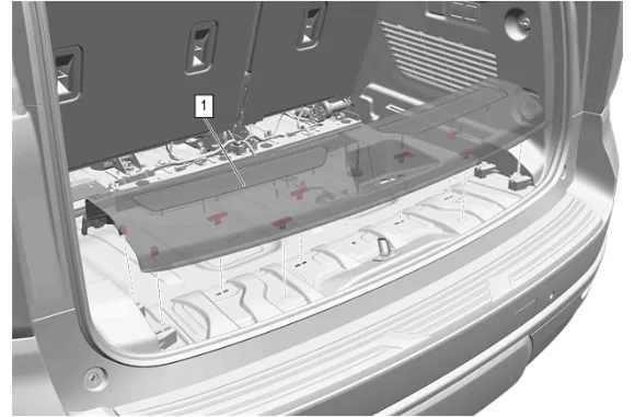
- Use a flat bladed plastic tool to disengage retaining clips on the rear end trim finish panel (1).
- Rear End Trim Finish Panel Opening Cover (1) » Remove
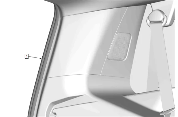
- Reposition the liftgate weatherstrip (1).
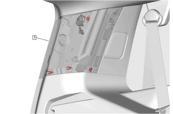
- Use a flat-bladed plastic trim tool to disengage the body side rear window garnish molding (1) and retaining clips.
- Reposition the body side rear window garnish molding (1).
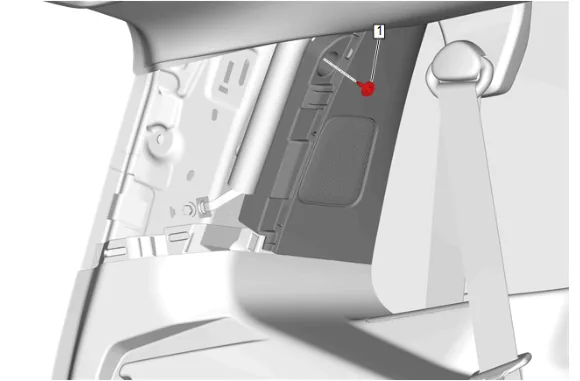
- Remove the body rear corner upper garnish molding bolt (1).
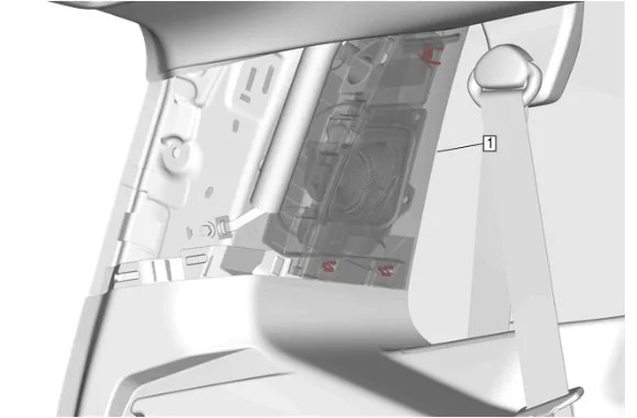
- Use a flat-bladed plastic trim tool to disengage the body rear corner upper garnish molding (1) and retaining clips.
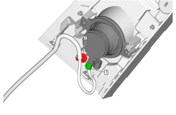
- Disconnect the electrical connector (1).
- Remove the wiring harness retainer (2).
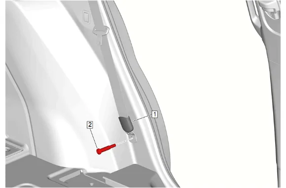
- Reposition the rear seat belt retractor sleeve (1).
- Remove the rear seat belt anchor plate bolt (2).
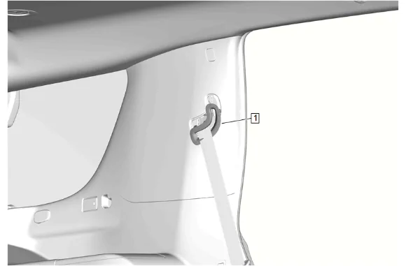
- Disengage the rear seat belt opening bezel (1).
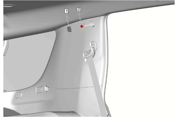
- Remove the quarter window trim finish panel bolt cap (1).
- Remove the quarter window trim finish panel bolt (2).
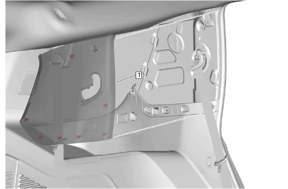
- Use a flat-bladed plastic trim tool to disengage the body lock pillar upper trim panel (1) and retaining clips.
- Feed the rear seat belt opening bezel and rear seat belt through the body lock pillar upper trim panel (1) and remove.
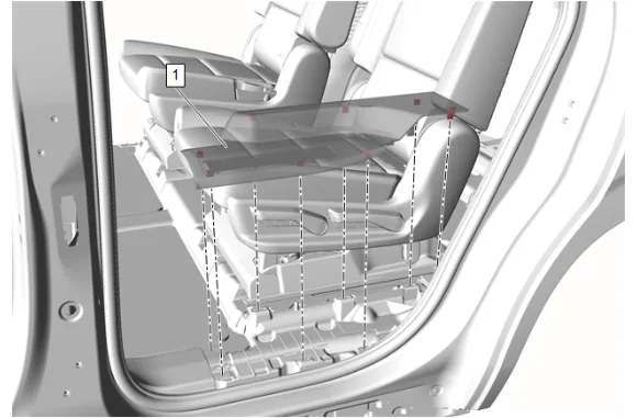
- Use a flat bladed plastic tool to disengage retaining clips between the Rear Side Door Sill Garnish Molding (1) and the Center Pillar Lower Trim Panel.
- Pull upward from both sides of the Rear Side Door Sill Garnish Molding to disengage retaining clips front to rear.
- Rear Side Door Sill Garnish Molding (1) » Remove
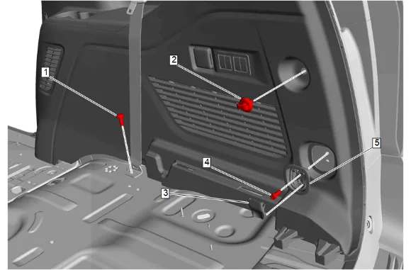
- Rear Seat Shoulder Belt Anchor Plate Bolt (1) » Remove
- Convenience Net Retainer (2) » Remove
- Cargo Tie Down Loop Bolt Cap (3) » Remove
- Cargo Tie Down Loop Bolt (4) » Remove
- Cargo Tie Down Loop Anchor Plate (5) » Remove
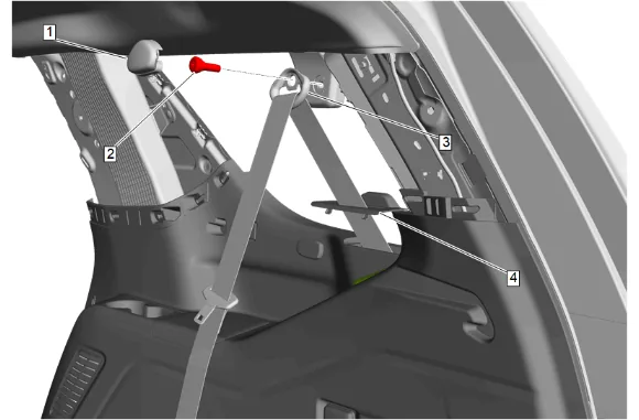
- D-ring Cover (1) » Remove
- Rear Seat Belt Guide Bolt (2) » Remove
- D-ring (3) » Remove
- Rear Seat Belt Opening Bezel (4) » Remove
- Feed the seat belt through the quarter lower rear trim panel bezel opening.
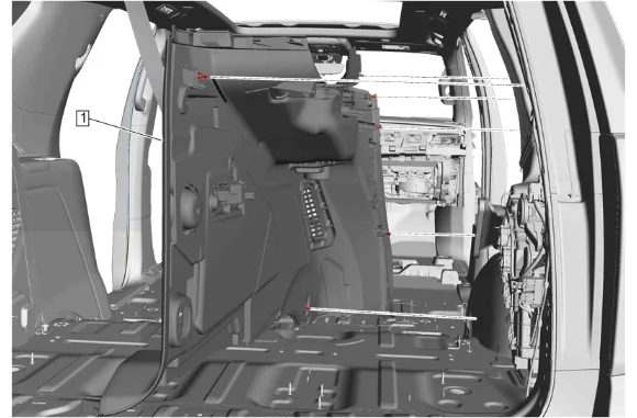
- Quarter Lower Rear Trim Panel (1) » Remove
- Disconnect the electrical connectors.
-
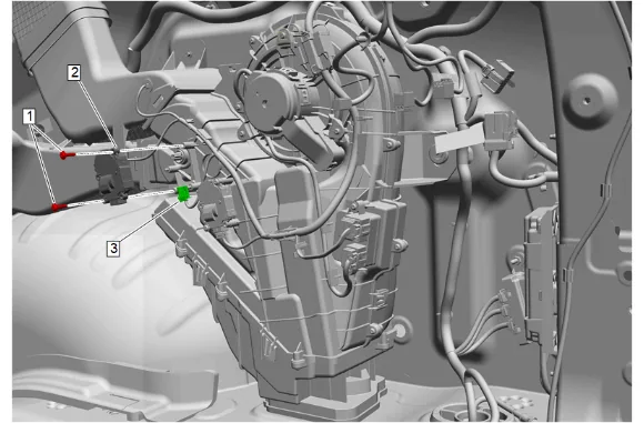
Auxiliary Air Conditioning Evaporator and Blower Module Bolt (1) » Remove [2x]
-
Rear Programmable Mode Valve Actuator (2) » Remove
-
Disconnect the electrical connector. (3) Installation Procedure
-
Connect the electrical connector. (3)
-
Rear Programmable Mode Valve Actuator (2) » Install
-
Auxiliary Air Conditioning Evaporator and Blower Module Bolt (1) » Install and tighten [2x] — Fastener Specifications
-
Connect the electrical connectors.
-
Quarter Lower Rear Trim Panel (1) » Install
-
Feed the seat belt through the quarter lower rear trim panel bezel opening.
-
Rear Seat Belt Opening Bezel (4) » Install
-
D-ring (3) » Install
-
Rear Seat Belt Guide Bolt (2) » Install and tighten — Fastener Specifications
-
D-ring Cover (1) » Install
-
Cargo Tie Down Loop Anchor Plate (5) » Install
-
Cargo Tie Down Loop Bolt (4) » Install and tighten — Fastener Specifications
-
Cargo Tie Down Loop Bolt Cap (3) » Install
-
Convenience Net Retainer (2) » Install and tighten — Fastener Specifications
-
Rear Seat Shoulder Belt Anchor Plate Bolt (1) » Install and tighten — Fastener Specifications
- Rear Side Door Sill Garnish Molding (1) » Install
- Feed the rear seat belt opening bezel and rear seat belt through the body lock pillar upper trim panel.
- Engage the body lock pillar upper trim panel (1) and retaining clips.
- Install and tighten the quarter window trim finish panel bolt (2). Fastener Specifications
- Install the quarter window trim finish panel bolt cap (1).
- Engage the rear seat belt opening bezel (1).
- Install and tighten the rear seat belt anchor plate bolt (2). Fastener Specifications
- Reposition the rear seat belt retractor sleeve (1).
- Install the wiring harness retainer (2).
- Connect the electrical connector (1).
- Engage the body rear corner upper garnish molding (1) and retaining clips.
- Install and tighten the body rear corner upper garnish molding bolt (1). Fastener Specifications
- Engage the body side rear window garnish molding (1) and retaining clips.
-
Reposition the liftgate weatherstrip (1).
-
Rear End Trim Finish Panel Opening Cover (1) » Install
-
Liftgate Lock Striker Cover (1) » Install
-
Install the 3rd row seat. 3rd Row Seat Removal and Installation
-
Enable the SIR System. SIR Disabling and Enabling