Engine Component Description (1)
Engine Mechanical - 5.3L L84 or 6.2L L87 | Description and Operation | Document ID: 5003100 Engine Component Description The 5.3 and 6.2 Liter V8 Engines
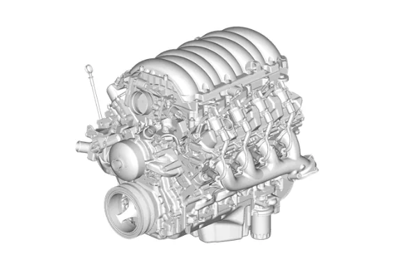
To assist in determining the applicable hardware and control system for each engine RPO, refer to Engine Content Specifications. Camshaft and Drive System – RPO L84/L87 A billet steel 1-piece camshaft is supported by 5 bearings pressed into the engine block. The camshaft has a tri-lobe forward of the rear journal for actuating the direct injection fuel pump. The CMP actuator is mounted to the front of the camshaft and retained by the CMP solenoid valve. The CMP actuator is driven by the crankshaft sprocket through the camshaft timing chain. The CMP sensor wheel is incorporated into the front face of the CMP actuator with the CMP sensor and CMP actuator magnet mounted in the engine front cover. A timing chain tensioner is mounted to the front of the engine block above the crankshaft sprocket. The externally splined crankshaft sprocket is positioned to the crankshaft by a key and keyway. The crankshaft sprocket external splines drive the oil pump drive gear. A retaining plate mounted to the front of the engine block maintains camshaft location. Camshaft Position Actuator and Solenoid Valve Description Crankshaft L84 The crankshaft is made of cast nodular iron. The crankshaft is supported by 5 crankshaft bearings. The bearings are retained by crankshaft bearing caps which are machined with the engine block for proper alignment and clearance. The crankshaft journals are undercut and rolled. The center main journal is the thrust journal. A CKP reluctor ring is press-fit mounted at the rear of the crankshaft. The reluctor ring is not serviceable separately. Crankshaft L87 The crankshaft is made of hardened forged steel. The crankshaft is supported by 5 crankshaft bearings. The bearings are retained by crankshaft bearing caps which are machined with the engine block for proper alignment and clearance. The crankshaft journals are undercut and rolled. The center main journal is the thrust journal. A CKP reluctor ring is press-fit mounted at the rear of the crankshaft. The reluctor ring is not serviceable separately. Cylinder Heads The cylinder heads are cast aluminum and have pressed in place powdered metal valve guides and valve seats. The valve rocker arm covers are retained to the cylinder head by 10 perimeter mounted rocker arm cover bolts. Cylinder heads are a high-flow design with offset intake valve rocker arms. Engine Block The engine block is a cam-in-block deep skirt 90 degree V-configuration with 5 crankshaft bearing caps. The engine block is cast aluminum. The 5 crankshaft bearing caps each have 4 vertical M10 and 2 horizontal M8 mounting bolts. The camshaft is supported by 5 camshaft bearings pressed into the block. The left bank of cylinders are number 1-3-5-7 (#1 is front left) and the right bank of cylinders are 2-4-6-8 (#2 is front right) viewed from the flywheel end of the engine. The engine firing order is 1-8-7-2-6-5-4-3. Exhaust Manifolds The exhaust manifolds are a 1-piece cast iron design. The exhaust manifolds direct exhaust gasses from the combustion chambers to the exhaust system. Each manifold also has an externally mounted heat shield that is retained by bolts. Intake Manifold The intake manifold is a 1-piece composite design that incorporates brass threaded inserts for mounting the throttle body, and wire harness studs. Each side of the intake manifold is sealed to the cylinder head by 8 silicone push in place gaskets. The electronically actuated throttle body bolts to the front of the intake manifold. The throttle body is sealed by a 1-piece push in place silicone gasket. The intake manifold covers the direct injected fuel rail assembly, fuel pipes and fuel pump. The manifold absolute pressure (MAP) sensor is installed and retained to the left front of the intake manifold behind the throttle body. The evaporative (EVAP) emission canister purge solenoid valve is mounted left front of the intake manifold below the MAP sensor. Fuel System The fuel system consists of 8 separate direct injection fuel injectors, two high pressure fuel rails, a high pressure cross-over fuel pipe (connects the two fuel rails), a high pressure fuel feed pipe (connects the cross-over pipe to the high pressure fuel pump), a high pressure fuel pump and a low pressure fuel feed pipe. The injectors are each seated into their individual bores in the cylinder heads with two combustion seals to provide sealing. The high pressure fuel pump mounts to the rear of the Valve Lifter Oil Manifold in the engine valley. Motion is transmitted to the pump from a tri-lobe on the rear of the camshaft through a hydraulic roller lifter. Oil Pan The structural rear-sump oil pan is a one-piece cast aluminum design. Incorporated into the design is the oil filter mounting boss, drain plug opening, baffle, oil deflector, oil pump screen, and oil level sensor. The oil filter bypass valve is in the oil filter assembly. The oil pan is sealed to the oil pump with a silicone push in place gasket and to the engine block with RTV sealant. Dowels are pressed into the pan for aid in alignment to the engine block during assembly. Piston and Connecting Rod Assembly The pistons are cast aluminum. The pistons use 2 compression rings and 1 oil control ring assembly. The piston is a low friction, lightweight design with a recessed top and barrel shaped skirt. The piston pins are chromium steel and are a full-floating design. The connecting rods are powdered metal. The connecting rods are fractured at the connecting rod journal and then machined for the proper clearance. All applications use a piston with a graphite coated skirt. The piston and pin are to be serviced as an assembly. Valve Rocker Arm Cover Assemblies The valve rocker arm covers are cast aluminum and use a pre-molded silicon gasket for sealing. Mounted to each rocker cover are the coil assemblies. Incorporated into the left and right valve rocker arm covers are the positive crankcase ventilation (PCV) fresh air passages. Incorporated into the left cover is the oil fill tube. Valve Train – RPO L84/L87 Motion is transmitted from the camshaft through the hydraulic roller valve lifters and tubular pushrods to the roller type rocker arms. The nylon valve lifter guides position and retain the valve lifters. The valve rocker arms are mounted on individual pedestals or pivot supports that are incorporated into the cylinder heads. Each rocker arm is retained by a bolt. Valve lash is net build. Each of the 8 cylinders can be deactivated individually via oil control solenoid valves mounted in the engine block valley. Cylinder Deactivation (Active Fuel Management) System Description